This article is about one of my recent spontaneous projects. A few days ago, I got lucky on an ebay auction and picked up a broken Acer K330 projector. I often look for these kinds of offers because I have spent several years in the audio/video repair business and am pretty confident in my skills when it comes to fault-finding. So I figured, saving some money by restoring a broken device couldn’t hurt.
First some facts and features: The K330 uses a three color LED module, which promises a long lifetime and low energy consumption. A Texas Instruments DLP module handles image generation. In sum this lets me hope for good contrast and strong colors, even if the brightness of 500 lumens doesn’t seem that much. An interesting thing about this DLP chip is that it uses an uncommon diamond pixel grid for size reasons. Diamond in this context means that the pixels do not form a rectangular pattern like in the usual TFT monitors but rather a grid of 45° rotated and slightly squeezed, not completely rectangular tiles. Of course, this means that internal resampling has to occur to map the image from the rectangular domain onto the diagonal domain of the IC.
So, this projector was obviously broken when it arrived – what a surprise. The seller had already informed me that it had suffered from overvoltage of unknown cause. The VGA picture was supposed to be very green-ish, the HDMI input dead in whole and the media player erratic. A slight flickering in the picture was also mentioned. I’ll take you through the repair process for this device from here on.
Arrival / Testing
I first plugged in the device in and turned it on, since it wasn’t supposed to be totally dead. This is usually not a good idea if the device has a known power supply fault since things might get worse when the high voltage hits damaged parts. I decided to trust the seller on this part, and as expected, the projector started up in a few seconds and decorated my wall with a bright and colorful standby screen. No obvious dead pixels and all three main colours were present, which meant that the digital mirror device (DMD) and the LED light source including the drive circuits for both probably survived. So far, so good. The power supply could still be damaged of course, but I didn’t expect that. From my experience, overvoltage failure on switchmode supplies (SMPS) is pretty much binary failure. The good ones have a varistor protection following the input fuse, which means the fuse blows when the varistor trips – sometimes together with the varistor. No big damage, but it’s dead. The cheaper ones do not have the varistor and sometimes a bad/slow fuse, which prevents shutdown and causes the primary rectifier to fail, the primary smoothing cap to blow up, or kills the drive circuit. Also, dead. This one was running smoothly, so it should be fine.
Then I also tested the inputs, but nothing new there. VGA only green, HDMI nonresponsive, media player behaves erratic, hangs and crashes. Composite works, though, but with the horrible image quality you’d expect from such a technological dinosaur. Also present is the slight flicker, but only when selecting HDMI in – strange!
Let’s crack this thing open.
Disassembly
The usual word of warning: Whether you do or don’t try the following is your responsibility alone! Usually, repairs of such devices are not for the hands of unexperienced people, which is not meant to be a discouragement in general. Just be aware of your limit and remember that live current can and will bite you if you are not careful and certain in your procedures.
While examining the case, I noticed that someone had already tried opening it before. Unfortunately, he seems to have made a bad choice about his point of entry and lifted up the white top section of the case, which is supposed to be welded to the rest. Well, the few scratch marks can be fixed and the cosmetic damage is not too bad. This is how it’s done the right way:
- Turn over the device. Remove the two lightly glued rear rubber feet by prying them out at the edge with your fingernail or a plastic tool. Also remove the two circular silver patches on the silver border toward the front of the device. Remove the four screws you find beneath.
- Pull the bottom plate toward the rear side of the projector. It should slide a few millimetres, then you can pull it off.
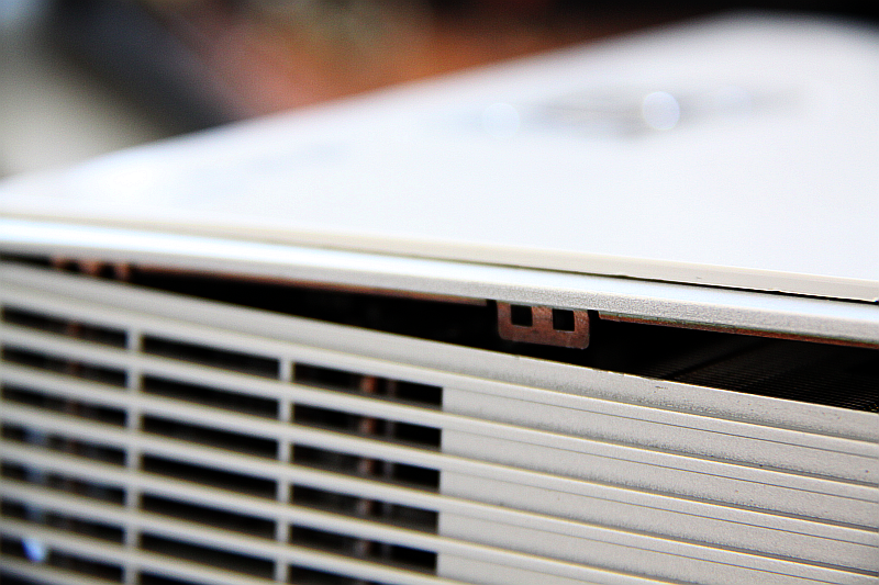
- Use a small screwdriver and pry up the top panel of the projector along the upper side of the first slit in the silver outer shell! NOT (!) the white part at the top, it is welded on. Force the silver top up with your fingers at the front left/right edges, then slide your tool into the slit near the holding tabs as a lever and push the silver side panel outwards to release the tabs. See the picture below to see how the locking mechanism works. There are five tabs inside, one at the front center, two at the left/right centers and two more aligned towards the rear of the case. Once all are unlocked, leave the lid in place.
- Pry out the holding tabs at the rear side carefully using only your fingers! Once all are removed, pull up and back on the top panel until it snaps off. NOTE THE FRAGILE RIBBON CABLE!
- Remove the ribbon cable. Note that the projector works without the top panel attached, using only the remote.
|
|
|

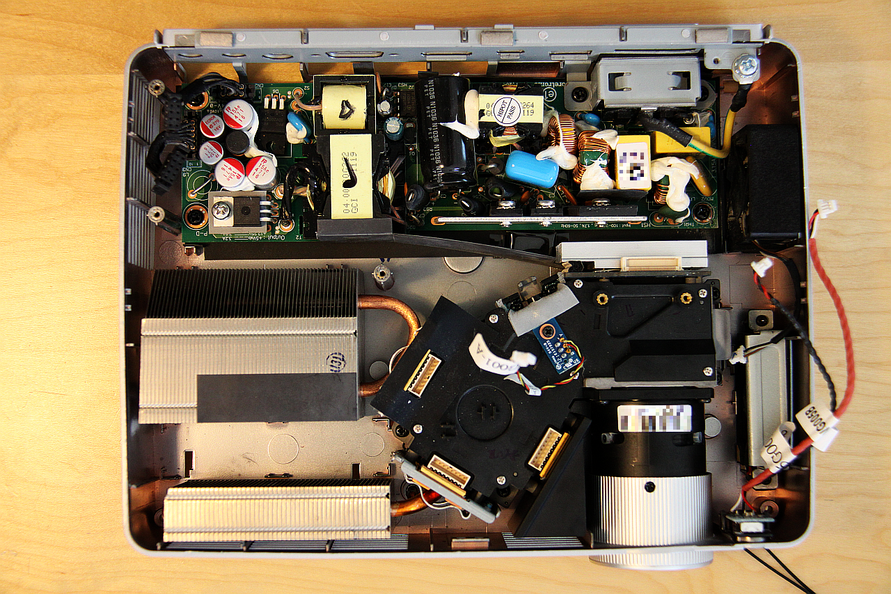
This is what it looks like on the inside:

The big blue board contains all the digital logic while the small one contains the power circuits for the lamp unit. To remove the logic board, first unscrew the LED power board and carefully pull it up. Note the small pin header connector (LED control) and the locked power connector at the bottom. Unplug these two, leave the LEDs connected and push the board out of the way. Now unscrew the four visible screws on the logic PCB and the two bolts securing the VGA port to the case backside. Stick your finger in the small space visible between the speaker and the fan (exactly centered on the right side of the case in the above picture) and pull the board upwards gently. The two PCB mounting screws behind the lens assembly mark the spot where the DMD connector is at the bottom side (see following pictures), it should unplug easily. Take care when remounting! Finally, carefully unplug the power connector (top left, see next picture). Depending on your plans, you might need to remove the remaining connectors, but don’t worry – the sockets on the PCB are marked, and it is pretty obvious which goes where.
Hint: When remounting the logic board, take care of the calibration/check light sensor! It is mounted on a small PCB below the logic board, right on the light channel. It has a three wire cable which is pretty fragile. If the device turns on, beeps several times, turns off and signals “LAMP” failure, check the cable where it is soldered to the PCB. It can easily short out and will produce the described symptoms.
The supply is underneath the whole logic unit, and, according to a visual check, no overheating or capacitor-splattering has occured here.
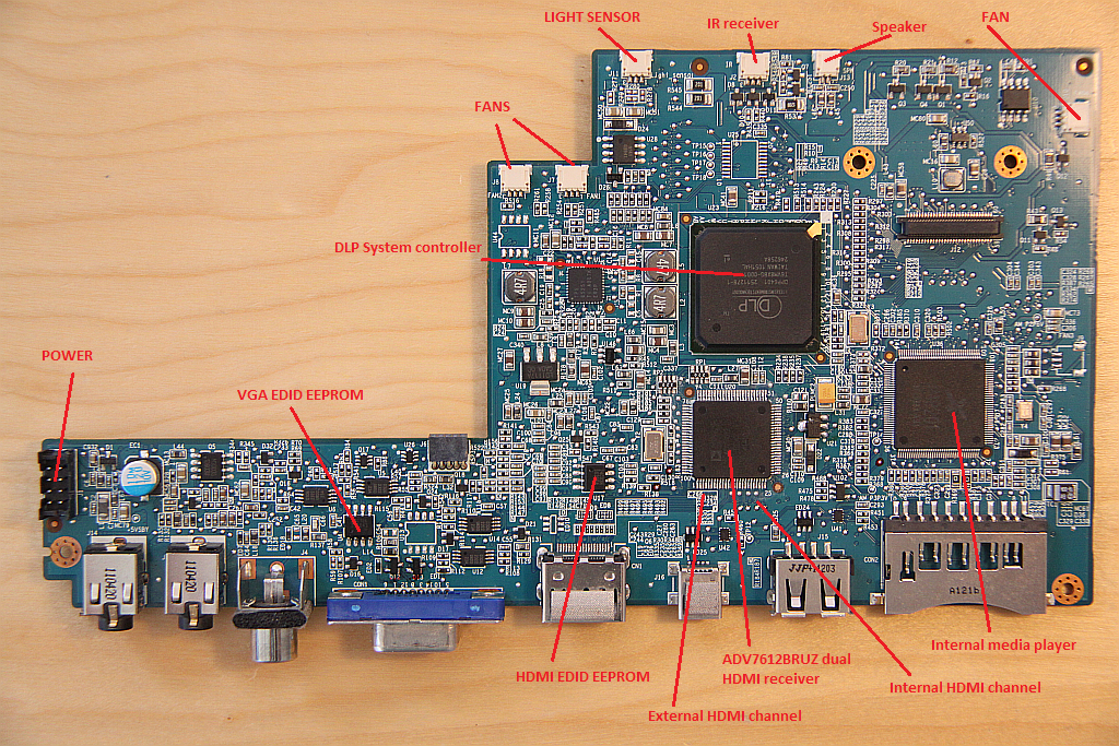
Let’s start off with a brief function block overview of the logic PCB since no schematic is available so far. I mostly “read” that from the circuit by looking for datasheets of individual ICs, then sorting out which interface goes where and more along those lines.
|
|
|

Fixing the VGA port
First up is the VGA port because the analog side is usually the most simple. Since the projector shows only green components, it seems like something has killed the red and blue channel, which is consistent with the idea of a voltage spike rolling in through the attached video source devices. Low signal voltage video inputs are usually equipped with some kind of buffering or protection circuit to prevent damage by electrostatic discharge (ESD), e.g. when touching the open plug while changing connections. There might be a voltage-tolerant transistor buffering stage or a bunch of clamping diodes.
 VGA input circuit, top side VGA input circuit, top side |
 VGA input circuit, bottom side VGA input circuit, bottom side |
Now, a closer look at the PCB area just behind the 15-pin D-SUB connector revealed several identical SOT-23 SMD parts. From googling the marking codes A7W, I expected them to be either dual diodes or NPN BJTs. A diode makes more sense in this place since there is no collector or emitter resistor present. This pretty much makes the use as a buffer impossible. Also, the parts are denoted as “Dxx” on the board, so diodes it is. A quick measurement of the two separate diodes in each device (one from signal to VCC and one to GND) shows three of the pairs totally open and one with erratic values (~30…130 mV diode voltage), with the erratic one being coupled to the red line. This looks like a strong high voltage spike has hit the device and has been shorted by the diodes. Unfortunately, diodes should normally be short-on-fail, which means that IF they are destroyed, they usually short out instead of opening up. This is not a good sign, as is the not completely shorted one, because a high voltage component might have gone through in this case. I replaced the diodes with matching ones from my parts bin (which was quite the surprise for me, I never thought I really had those). Hot air soldering is recommended for this kind of work, and you should probably select a higher temperature to keep your soldering time short. The solder on this board is high-melting lead-free, which is really the worst for reworking, and the board has lots of ground layers.
After this step, the picture became green-blue. No red. Further oscilloscope-aided inspection along the signal trace shows that the signal arrives at the digital converter IC, but the input shows different impedance in comparison to the other two colours. So, I guess it is broken inside the IC. The TI AFM1000 is a custom made device which means there will be little chance of getting one from the usual suppliers, and I don’t want to look into the asian backchannel markets just because of a VGA port right now.
Fixing the HDMI port
Since HDMI is a high speed, low voltage differential signalling (LVDS) type bus, its input circuits are even more sensitive to ESD. It also has protection devices, which can be seen as long, thin plastic packages just behind the HDMI port (marking on PCB says “ED###”, probably for ESD diode):
 All of these were unsoldered using hot air and measured outside the circuit. They usually consist of a pair of clamping diodes followed by an integrated common-mode suppression coil, but in this case there is only the diode part. Surprisingly, they all appeared okay. I left them outside for the moment, which was partly because these things are TINY! Even the weakest setting of the hot air tool blows them miles off the board. A reflow oven technique could be used for this, but I wasn’t sure if the larger devices are securely glued to the board. I had this happen to me once ages ago, and believe me, you don’t want to see your own face when the whole underside of your populated PCB goes *plunk* in the oven tray…but now, back to business.
At this point, I plugged in an HDMI source – my notebook – and again, nothing happened. After following some of the traces around on the board, I noticed, that the media player section also feeds its output into the same dual-line HDMI receiver IC (Analog Devices ADV7612). Strange, I thought I got short flashes of good picture from the media player earlier. So, the HDMI can’t be totally dead, can it? But how is it possible that the notebook does not even notice the hotplug event?
Measuring the external HDMI signal and hotplug-data lines for conductivity against ground reveals a low resistance of 5 ohms where the supposedly good port has resistances decades higher. Whoops, this looks like an internal short somewhere. To be sure, I unsoldered everything that was connected to the external HDMI signal path, just to be sure. Well, I have to admit, putting all that 0603 sized stuff back afterwards was a real pain, and the results didn’t change. This led me to an idea. Fortunately, I have access to a good thermal imaging cam with close-in focus, which I used to look at the PCB. In operation, the whole HDMI receiver region emits a LOT of heat, and especially the voltage regulators of the Analog Devices IC. I’ll add the thermal picture once I manage to find out which folder the cam has dumped it into.
As a test, I froze those with cooling spray – and just like that, the screen became dark and the media player popped up, nice and stable. I could even watch some short movies while cooling the IC with some more spray, but if it got a little bit too hot the player would crash at once. So, my guess is the following: The HV spike somehow went past the diodes and hit the input circuits of the IC. The parts connected to the external HDMI line were shorted out to ground and VCC when the internal transistors went down, and the remaining 5 ohms are probably substrate resistance and bonding wires. The chip can still work on the good HDMI line because of separate circuits, but the short increases its power consumption to the maximum available from the regulator, which then runs into temperature current limit. At this point, the picture either starts flickering if external HDMI is selected, or the media player picture starts hanging.
My first (and temporary) solution was to solder a small cooling fin made of a piece of copper sheet onto the ground connector of the regulator. It is necessary to isolate the surrounding parts with a piece of plastic sticky tape or the likes. Afterwards, the media player function can be used perfectly fine, if the cooling mode of the projector is set sufficiently high. If the regulator gets too hot, the picture immediately starts hanging.
The long-term solution requires a new IC. This one is pretty difficult to get if you don’t want to pay the price for a new projector, but RS Components has it in stock for a fair price. They even supply the type with hardware HDCP keys (ADV7612BSWZ without the -P), so I will not get into trouble when connecting an external blu-ray player if I manage to get and fix a broken one at some time in the future ;-)
Swapping the IC is again done using hot air. The thermal pad is a bit tricky, but since the IC is done for anyways, I hit it right in the middle with 500°C until the pad below melted. A reflow oven doesn’t help, unfortunately, since the components don’t seem to be glued to the PCB. After removal, the pads are first cleaned and fluxed, then the new IC is installed. Re-soldering is also a tricky job which I accomplished using a Weller WS50 fine-tipped soldering iron, flux and desoldering wick in combination. The bottom pad can be soldered using hot air, or you put on a small and flat bead of solder and press the IC down on it, while soldering it all around. Not the best style, I know, but the IC doesn’t really seem to need the cooling – which I checked afterwards.
Unexpected consequences…
After all this work, I half expected a crisp, clear picture to pop up when plugging in the HDMI cord. Nope. Argh! The notebook still doesn’t even notice the device. But wait a second, how does it even do this? Usually, there should be a device identification (EDID) module attached to the port that tells the source what is happening at its port. It also contains valid resolution/timing and transfer mode properties. And guess what, this one is dead, too. Seems like this line also got hit by the spike.
I cross-checked the 24C02 EEPROM (next to the ADV7612) outside the PCB with a diode tester, between ground and the data lines. A good one shows no conductivity, this one does. This is bad, because even if a new chip is easy to obtain, the data is inside the old chip – and we can’t clone it! At this point a little luck helped: The (dead) VGA port had an identical method of informing the attached master (well, as the standard dictates it). So, what would happen if we swapped the VGA EEPROM onto the HDMI port? Damage is not very likely, and in the worst case the settings are simply crap – so I just tried it. And guess what, it worked right off the spot.
 Of course there is a reason for this: Both systems follow the EDID standard, although the EDID signal also contains some information about the connection between source and sink, which might be invalid after the swap. The source device on the other hand can just ignore the obvious wrong parts, depending on the driver. I dumped the information using the NVIDIA driver of my notebook and analyzed the saved dump using the Wikipedia article about the EDID format:
According to this the K330 informs the master about an analog connection. The notebook simply ignores this, but my WDTV Live box for example doesn’t. This causes a warning about bad resolution selections, and I would bet that some of the 3D features of the projector (120Hz mode in full 720p) are lost, too.
This leaves three ways out:
- Fix the old EEPROM (unlikely since dead).
- Find a good dump of the HDMI EEPROM and flash that into mine.
- Reconstruct something fitting from the standard documentation.
I decided to go with the last option, but for this, access to the EEPROM was needed. As the IC is on the underside of the main PCB, this would be tricky even when the case is open. Still, one can avoid soldering wires: Remember that the EEPROM is already connected to the external HDMI port! During operation, the connected source device would act as a I2C bus master and talks to the EEPROM, reading out the ID information. This can also work the other way around! There are tools for Windows and especially for Linux (i2c-tools) that can write to almost any I2C device that is attached to an internal or external bus, in this case the GPU I2C. An example shows how you can do that in Archlinux:
1 2 3 4 5 6 7 8 9 10 11 12 13 14 15 16 17 18 19 20 21 22 23 24 25 26 27 28 | # pacman -Sy i2c-tools ... <installing messages, etc> # modprobe i2c-dev # i2cdetect -l i2c-0 i2c Radeon i2c bit bus 0x90 I2C adapter i2c-1 i2c Radeon i2c bit bus 0x91 I2C adapter i2c-2 i2c Radeon i2c bit bus 0x92 I2C adapter i2c-3 i2c Radeon i2c bit bus 0x93 I2C adapter i2c-4 i2c Radeon i2c bit bus 0x94 I2C adapter i2c-5 i2c Radeon i2c bit bus 0x95 I2C adapter i2c-6 i2c Radeon i2c bit bus 0x96 I2C adapter i2c-7 i2c Radeon i2c bit bus 0x97 I2C adapter i2c-8 i2c card0-DP-1 I2C adapter i2c-9 smbus SMBus I801 adapter at 0400 SMBus adapter # i2cdetect 2 WARNING! This program can confuse your I2C bus, cause data loss and worse! I will probe file /dev/i2c-2. I will probe address range 0x03-0x77. Continue? [Y/n] y 0 1 2 3 4 5 6 7 8 9 a b c d e f 00: -- -- -- -- -- -- -- -- -- -- -- -- -- 10: -- -- -- -- -- -- -- -- -- -- -- -- -- -- -- -- 20: -- -- -- -- -- -- -- -- -- -- -- -- -- -- -- -- 30: -- -- -- -- -- -- -- -- -- -- 3a -- -- -- -- -- 40: -- -- -- -- -- -- -- -- -- -- -- -- -- -- -- -- 50: 50 -- -- -- -- -- -- -- -- -- -- -- -- -- -- -- 60: -- -- -- -- -- -- -- -- -- -- -- -- -- -- -- -- 70: -- -- -- -- -- -- -- -- |
I figured out which bus was my GPU DVI bus and which device on it the projector by trial and error. After I had this info, I read the EDID directly from the device:
1 2 3 4 5 6 7 8 9 10 11 12 13 14 15 16 17 18 19 20 21 22 23 24 25 26 27 28 29 30 | # i2cdump 2 0x50 No size specified (using byte-data access) WARNING! This program can confuse your I2C bus, cause data loss and worse! I will probe file /dev/i2c-2, address 0x50, mode byte Continue? [Y/n] y 0 1 2 3 4 5 6 7 8 9 a b c d e f 0123456789abcdef 00: 00 ff ff ff ff ff ff 00 04 72 23 12 42 b0 0a 00 ........?r#?B??. 10: 22 15 01 03 6a 00 00 78 0a d7 76 b2 4a 25 c5 24 "????..x??v?J%?$ 20: 05 51 5b 3f cf 80 31 7c 45 7c 61 7c 81 c0 95 00 ?Q[???1|E|a|???. 30: b3 00 01 01 01 01 9e 20 00 90 51 20 1f 30 48 80 ?.????? .?Q ?0H? 40: 36 00 00 00 00 00 00 1c 00 00 00 fd 00 32 78 1e 6......?...?.2x? 50: 64 0f 00 0a 20 20 20 20 20 20 00 00 00 fc 00 41 d?.? ...?.A 60: 63 65 72 20 4b 33 33 30 0a 20 20 20 00 00 00 ff cer K330? .... 70: 00 4a 43 4e 30 31 30 30 31 35 39 30 31 0a 01 18 .JCN010015901??? 80: 02 03 04 00 66 21 56 aa 51 00 1e 30 46 8f 33 00 ???.f!V?Q.?0F?3. 90: 00 00 00 00 00 1e 00 00 00 00 00 00 00 00 00 00 .....?.......... a0: 00 00 00 00 00 00 00 00 00 00 00 00 00 00 00 00 ................ b0: 00 00 00 00 00 00 00 00 00 00 00 00 00 00 00 00 ................ c0: 00 00 00 00 00 00 00 00 00 00 00 00 00 00 00 00 ................ d0: 00 00 00 00 00 00 00 00 00 00 00 00 00 00 00 00 ................ e0: 00 00 00 00 00 00 00 00 00 00 00 00 00 00 00 00 ................ f0: 00 00 00 00 00 00 00 00 00 00 00 00 00 00 00 ab ...............? # i2cset -f 2 0x50 0x14 0x81 b WARNING! This program can confuse your I2C bus, cause data loss and worse! DANGEROUS! Writing to a serial EEPROM on a memory DIMM may render your memory USELESS and make your system UNBOOTABLE! I will write to device file /dev/i2c-2, chip address 0x50, data address 0x14, data 0x81, mode byte. Continue? [y/N] y Error: Write failed |
The last command instructs the I2C driver to write a value of 0x81 into the byte address 0x14 of the device 0x50 on bus 2 (i2c-2). The value is arbitrary though, it was just a test – and it failed, because the EEPROM inside the projector was write protected as it should be. At this point, I put in a small modification to unlock the EDID memory. The picture below shows where to place the solder bridge to short the write protect pin to ground. Convenient of Acer to leave these resistor soldering pads open in the perfect spot.
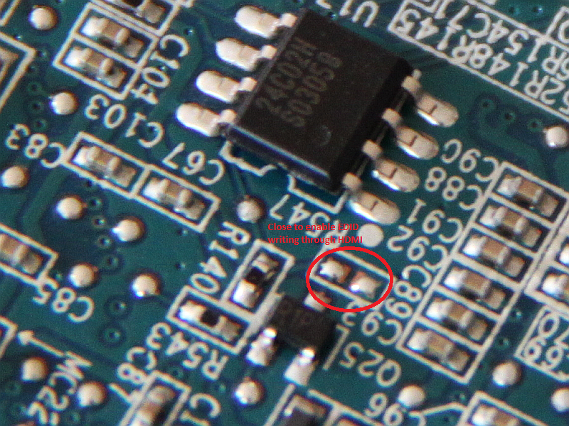 EDID EEPROM solder bridge EDID EEPROM solder bridge |
Electrically, this is completely safe because the pull-up resistor of this line is at least 4,7k ohms (measured) and the transistor next to it would short the WP line to ground anyways. It can probably be controlled by the main CPU to allow for EDID updates when the firmware is flashed. After placing the bridge, I tried again:
1 2 3 4 5 6 7 8 | # i2cset -f 2 0x50 0x14 0x81 b WARNING! This program can confuse your I2C bus, cause data loss and worse! DANGEROUS! Writing to a serial EEPROM on a memory DIMM may render your memory USELESS and make your system UNBOOTABLE! I will write to device file /dev/i2c-2, chip address 0x50, data address 0x14, data 0x81, mode byte. Continue? [y/N] y # |
Strike! No error this time. A second inspection of the EEPROM dump revealed that the data had truly been stored, and a short call of xrandr showed a change in the device properties. Now I could close the casing and still be able to update the EDID if I need to later on. If your source device should not be able to do the programming, a simple I2C capable microprocessor and an HDMI cable adapter would also do the trick.
I still have to figure out the ideal data for the EEPROM, but this is a long-term target when problems arise. For now, I can attach any of my usual sources without problems. If any of you people reading this owns an Acer K330 and feels in the mood to drop me a hex dump of the original HDMI connection EDID in the comments below or via email (see contact page), I would appreciate it!
FOLLOW-UP: There is a copy of the K130 service manual available in the net which describes a procedure called “EDID key-in”. The correct factory procedure adapts a serial connection from the programming PC to the levels used in the HDMI/VGA DDC signals, which is ultimately equivalent to the procedure described above.
The more interesting part is about unlocking of the EDID write mode. As the manual states, hold the power key, then plug in power. Hold the key until it flashes blue rapidly (not red-blue-alternating, takes a second or two) then release it. The key will flash blue-blue-red in sequence. This is what I already suspected from the write protect lines of both EEPROMs leading to the core IC. I cannot test this because mine is already hard-patched now, but my K330 at least responds to this key combo in the way described. Since the firmware seems to be largely identical, the function should be the same as with the K130 – meaning you can reprogram the EEPROMs from the PC while the flashing of the LED continues, no soldering required. This may be a helpful trick for those trying to make their K330 fully 3D-compatible – there seems to be a lot of problems going on. Probably voids the warranty though. ;-)
One nice thing about rewriting the EDID is that the projector (or any unlocked EDID-capable device) cannot be bricked beyond recovery. I2C detection on the DDC bus works independently from display device recognition. If you probe the bus, the EEPROM will always be there waiting for commands, even if the contents are mostly corrupt.
I also got hold of a copy of the good HDMI EDID which will hopefully make my old Radeon graphics card recognize the projector. So far, it refuses to even detect its presence. Probably related to some bad EDID bits, but this makes the HD5770 the only source device in my reach that just plain rejects the projector without any debug info. Not a feature, AMD, not at all.
µ ~ 2014-12-29
It worked. The VGA EDID seems to be missing several extended descriptors necessary for HDMI and also some basic settings. Still, funny that only the Radeon noticed…
Audio through HDMI also works like a charm now.
µ ~ 2014-12-31
Forgot to mention which K330 HDMI EDID I used for the restoration. Click here to get the contents and here to see where I got it from. Note that I removed the serial number of the device from the file and replaced it with “– — — –“. Insert your own here, please. Wiki tells you how, or you extract it from your own device. Also keep in mind that the “real” S/N is stored elsewhere, so forging it won’t do ;-)
µ ~ 2015-10-26
Last but not least I checked the configuration of the projector through its service menu. To enter, press the sequence POWER, LEFT, LEFT, MENU either on the device itself or the remote – makes no difference. All further instructions are given in the menu. As far as I could see, there are not a lot of options that can brick the projector, except for the LED current programming which is better left alone! Excluding this, the menu features test pattern modes, several interesting options and diagnostic tools. I checked for any options to unlock the EDID ROM before soldering the contact bridge, of course.
Short recap:
- Bought an Acer K330 LED DLP projector as broken for roundabout 40 Euros.
- Fixed the VGA input circuitry, but VGA is still partially broken. No red colors.
- Composite input works, audio works.
- Removed the probably damaged HDMI ESD protection circuits. No replacement so far, will install some later on, but they are a pain to solder because of their small size and contact density. Until then, being careful and always plugging the projector HDMI in last and unplugging it first should prevent static from getting to the data pins.
- Replaced the HDMI receiver IC for ~13 Euros.
- Dropped the original HDMI EDID chip and swapped the (now useless) VGA EDID IC over. Probably suboptimal data, but it works.
- Modified the EDID write protect to always-writeable to allow editing over the HDMI cable.
- Strangely, the projector does not allow audio through HDMI. That is no big problem though, since I prefer optical connections for this.
Some useful hints for checking circuits:
- Checking BJT transistors in circuit can be done by testing the two diodes with a multimeter. Remember the circuit symbol: NPN (“not pointing in“) has two from base to C and E while PNP (“pointing in proudly“) has them reversed. Typically, the forware voltages should read ~500-900 mV depending on the type, and if both do, it is probably fine. Dead ones can show up as 0-200 mV or larger than 1800 mV. The reverse voltage should always measure larger than 1800 mV, infinity would be ideal. This method works in ~90% of all cases. BUT: Take care of any parts that are mounted in parallel to the diodes, like other reverse diodes. Usually, at least the reverse voltage reading will be off and the device will need to be removed for correct measurement. Keep in mind that the diode function is only one part of the whole, a transistor showing good diodes may still be broken! If further measurements indicate that something simply does not fit, desoldering of components or well-placed cutting of signal lines to isolate function blocks is needed.
- As already mentioned, it can be useful to disconnect function blocks from each other and test them separately. This works well with audio amplifiers: You can usually AC-separate consecutive amplifier stages at their coupling capacitors without breaking the DC bias conditions inside each block. Take care with open inputs as some stages may tend to oscillate without an attached source – these inputs could for example be terminated with 10 kOhms resistors. Again, take care of possible un-isolated bias voltages at the input!
- Trying to understand circuits without a schematic by just recognizing the basic function blocks (which you see everywhere) is good training for the brain. Do this more often, and you will see from experience, when a measurement in circuit is off.
- Search for redundant circuits or sections. Remember: Designers also like to copy&paste, which is why most devices that feature multiple channels of anything will have the same circuit for all channels. This gives you a useful chance for reference measurement while, for example, diagnosing the dead channel circuit in an audio amp.
- For hard cases, there is always the internet: Try to google/search for your device type number adding “service manual” or “schematic” and see if something useful comes up. For audio stuff it almost always does, video and digital equipment is rather rare.
- Always, always, ALWAYS unplug and discharge your circuit before doing continuity/diode measurements. Aside from all readings being off when the circuit has residual power, you put yourself and your meter at risk of shock damage – which should be kept in mind for all other work on circuits, too, of course!
With this I hope to have given you some insights, or an enjoyable read at the least. See you around!
Hi and thanks for your post, which helped me disassembled mine, which has the same issue as some with the lense which has burned (badly).
Has someone been able to find a replacement for this part? I tried using the videoprojector without this lense and i works, but obviously there is color issues on the sides.
Hello, great write-up with a lot of detail in the explanation.
I have a K330 that I have been using since 2012, so it has seen a lot of use.
The last year or so it has started having color issues when showing skin tones. Skin appears to be saturated and red. Everything else more or less looks fine.
That got me into looking at the settings that I am using, which I hadn’t looked for a long time
I am using the “bright” mode and changing it to any other mode except that such as “presentation”, “standard” etc makes everything very red.
The projector wall setting is “white”, if I change it to “purple” makes skin tone better but everything else turns blue.
Also the color templerature setting is on 1 (the middle setting) changing it to 0 or 2 makes everything red again
I managed to access the service menu and did some color tests, and I could see it can project the full range of colors.
I have been very satisfied with this projector and it is still working after all of this years, I just got curious what caused this issue will all settings except “bright” making colors shift to red
Thanks!
Hi,
since bright mode overdrives the LEDs, this could point to uneven aging of the three light sources. A purple image indicates weak green, which makes sense because green is used to create the “bright” effect. That should be noticeable in the service menu color test as a dim graduated green color bar. When cycling through mixed colors, yellow and cyan would not work out. I’ll assume you have already tried calibrating the LED from the normal on-screen menu.
What kind of video signal are you using (HDMI, VGA, …), and have your tried another video source and/or any other input on the projector? Your problem somehow sounds like part of the red color information might be missing, resulting in the projector receiving coarse color steps instead of finely graduated ones.
Hi,
after 10 years, few days ago I found the lamp warning led flashing…It means “lamp breakdown”
any suggestion?
Hi Roberto,
if all three LEDs do briefly come on when starting up, you might want to check the light sensor. Might be clogged up after all that time or have a bad wire. Some dust seems to have found its way there every time I open it up.
I am pretty certain the LED currents are monitored on the driver PCB, so either this or the light sensor must cause the error.
Hi, i have a k330 projector, It Powers on, but on the wall you sede only a white screen with grey and black Lines, like a sort of irregular grid, in your opinion what could be the problema? Do Toy think it’s fixable?
Thanks for your attention
Best regards
Stefano
Hi,
The brightness of my acer k330 became a very low. After disassembling I have found that the part in the red circle is melted http://imgur.com/a/xaNV6
What can be reason of that?
Could you help me with name of this part and replacemnet part number?
Thanks,
Yuriy
Hi,
unfortunately I don’t have a service manual, so I can’t tell you the part number. The part is a (micro-)lens array made of plastic. This should not melt since the majority of the heat is transferred off the LEDs by the heatsinks. If it does, I would expect loss of cooling. E.g. a dead fan or blocked radiator. Since the inside of the light channel is not actively cooled, ambient temperatures around the channel must have gone pretty high. The other possibility would be excessive dust buildup on the lens array which dissipates the light as heat on the plastic surface, but since the channel is sealed no dust should be able to enter – at least not in such a quantity.
Hi Yuriy,
Same for me. Did you finally find this part ?
Regards,
Fabrice
the same happens to me. Probably too much dust did not allow the right cooling, so that microarray of lens melted. I took it away, but it is useful to have a uniform lightning of the image.
I see you’re still actively opening up your K330. Is there any chance you could open up the lens housing and document with some photos, so that I can put my lenses back in correctly? It requires a full disassembly and reassembly to check one lens at a time, and quite a few possible combinations. I’ll surely break it before I find the right one by chance.
I am doing the cleaning today, so I will try to add that.
EDIT: Pictures will follow, but here’s a description of the lens alignment. Beginning from the LEDs, there is one half-spherical small lens for each that has its convex side pointing into the chamber. Each is followed by a second polymer half-spherical lens which is loosely inserted in the chamber. Those are also pointing inwards with the convex side. I can’t see any difference, so all of those are probably identical. In the center of the chamber sits the dichro mirror assembly, which cannot be reversed since it is held by coded pins. At the output of the mirror cross, a double planar microlens follows. I am guessing that the orientation of this one does not matter since it only mixes the light. Next is a glass lens which is FLAT on one side. This is the thinner of the two glass lenses, and the convex side points towards the LEDs, flat side towards the DMD. After this comes the alignable mirror (lossened that one, so I’ll have to readjust it – duh!) followed by another glass lens. This is the thicker one of the two. It is not symmetrical, one side is more curved than the other. The stronger curve goes towards the LEDs/mirror, the slightly curved side towards the DMD. What remains is only the DMD and its mirror housing which cannot be reversed and the projection lens itself. To take that one apart, I would have to move into my workplace’s cleanroom lab.
Hope that helps. Tell me if you need details. Also, maybe I am mistaken about the glass lenses being asymmetric. They might only appear this way when examined close up, but they do have a different thickness.
Really nice write-up on your repair! I have a K132 I bought (VERY cheap) on eBay as “dead”, but (like you) I decided to plug it in and try… worked perfect. However upon my first disassembly, I found an extra screw loose in there! I’m sure that it had previously found a place to lodge itself causing a short… but probably during shipment it freed itself. Just had to ass my own 19V laptop power supply and bought a remote… perfect! I was, however, very frustrated at Acer’s “no audio output” decision, other than their optional multifunction cable, which adds VGA input and audio output. This drive me to determine the connection points on that connector to grab R/L audio outputs, and add a 3.5mm stereo headphone jack to the back panel for “Audio Line output”… works great.
I saw a review on ProjectorCentral.com by a user who said he modified the light path by adding a piece of black paper inside the light engine, just in front of the projection lens with a 6mm x 8mm opening. Supposedly this greatly increased contrast by absorbing incident light reflecting around inside the metal housing. This will be my next mod… but I was hoping maybe someone reading this blog might have had their optical cavity open before… with pictures.
I have ‘external’ pictures of the optical cavity, but no way to attach them here… I’ll try links:
https://dl.dropboxusercontent.com/u/50213618/public/acerk132/IMAG0822.jpg
https://dl.dropboxusercontent.com/u/50213618/public/acerk132/IMAG0823.jpg
Thanks for sharing your experience :-)
Inserting an aperture into the light channel is a great idea! I’ll have to clean my projector soon anyways, might as well crack the channel open and have a look. I have had the feeling for some time that whenever the DMD displays dark scenes, the light which is dumped somewhere to the side accidentally still ends up on the screen. This might help indeed.
At the same time, I will have to find a solution for the cooling of the blue LED as it has the smallest and least efficient radiator and sits in a dead corner right beside the lens. Poor airflow there! Might be intended to become the lifetime-limiting factor at some point.
About the Blue LED heat sink being so small… I think this may help understand why:
https://goo.gl/iCSgb8 Pay specific attention to the small table – direct link here: https://goo.gl/4DWg2C
Typical RGB set of phlatlight LEDs: http://www.luminus.com/products/PT-40.html
With the Blue clear down at 460nm, there’s probably at least a 12:1 Green-to-Blue luminous flux ratio, and 5:1 Red-to-Blue ratio needed for D65. The Green will be the hardest hit, which by your picture, bears true by the Green LED heatsink size.
Assuming the PT40 RGB LED set (typical Current/Flux curves, operating voltages, etc), and my K132 which runs around 60 Watts input overall (leaving 10W for non-LED power), I estimate LED power (I*E) at: Blue=8.8W / Red=14.3W / Green=27W
The Red and Blue heatsinks get fresh/cool air, drawn into the projector by the exhaust fan. The Green has to deal with the fact that it get pre-warmed air from the Red heatsink, so it (Green heatsink) needs to be even larger than the 2:1 G:R power dissipation levels would indicate.
(sorry… we EE nerds always have to “math” things out)
Thanks for doing the math, I have to admit I was kind of too lazy to look up the numbers ;-)
Didn’t expect such a large difference in between the power levels, though.
First thing I have to do now is clean my DMD window. Seems like when I was trying to insert the aperture (which didn’t work so far, since you always have to disassemble and reassemble for alignment) some dust got in an settled on there. Should be no drama to fix that, focusing shows that it is not on the DMD surface but rather offset on the protective glass.
I was thinking that it might be sufficient to only shield the light trap to the left of the DMD with some black plastic, in a way that light can’t bounce off there. Acer seems to have done some attempts there, since the projection lens contains an aperture with a small circular shape on the side of the light trap.
updated image links after Dropbox made policy changes:
https://www.dropbox.com/s/mck6t0r9saz78z0/IMAG0822.jpg?dl=0
https://www.dropbox.com/s/05vdby6ftmsp7jb/IMAG0823.jpg?dl=0
I still haven’t made the contrast / aperture mod. This projector has seen a LOT of use in my “home theater” as my daily-use machine… to save hours on my Panasonic PT-AE2000. I designed and 3D printed a motorized mount for my Acer, so it gets lowered directly in front of my Panasonic:
https://www.dropbox.com/s/3cen5bnukzkx1a6/IMAG1250.jpg?dl=0
https://www.dropbox.com/s/qsy2o8ie8wboyq3/IMAG1252.jpg?dl=0
Other than the “thermal lens drift”, I’m well pleased with this tiny thing. I spent a fair amount of time adjusting the image controls, and ended up with a nice bright and well-saturated image. I use a 108″ “cinema grey” Da-Lite screen, but with the position of the Acer, I only get about a 90″ diagonal image. After the initial 10-15 minute warm-up, the lens stabilizes and does fairly well. I wish it had better optics, but hey… not bad for a US$35 “dead” projector. With a little larger cabinet, they could have made a nice Home Theater version with some zoom and lens shift.
Hi, I had same projector and i thing same problems, I thing I had damaged also part of light sensor monitoring, when i Run projector it starts up and after lights up then after 5seconds it turns off and show lamp error. I had tested, when i am fast and after start i go to service menu, and i manual calibrate led, it will show COMM_Error and projector dont turn off, and i can use it. I have write program on arduino and some simple circuit to control projector, so arduino starts projector, go to service menu and runs calibration. Then i can push resync and projector working. But, AV (composite) imput is dead, showing “No Signal”, VGA is also showing “No Signal” but PC it recognise and set resolution. On HDMI, when i connect satellite reciever, it works perfectly, but when i connect PC it cant recognise projector, PC giving me message that no another display is connected, So I found on PCB the 24c02 is broken, i bought new and tried to flash with this HEX file from you and not response, then i tried to clone my VGA eeprom to this HDMI eeprom it didnt worked. I thing sattelite reciever is giving signal to HDMI without any questioning of target device for resolution etc. So can you please help me ? Thanks
Your approach to the shutdown problem is quite interesting indeed :-)
I suspect that the VGA/AV are not working because they are handled by the same IC, and it might be possible that your device cannot finish initialization because of either the error or the early entry into the service menu. Possible, at least.
The HDMI is handled by an entirely different IC which does not necessarily need parameters from the microcontroller unit, which might explain why this works. The EDID EEPROM is read directly by the computer, the projector does not influence that except if it is programming the EEPROM (which happens only upon firmware updates or manually as described in the post). Many consumer devices do not read it or need its data, which seems to be the case for your sat receiver. If the PC cannot read the new EEPROM, the remaining I2C connection on the projector mainboard must be damaged. This means either the line driver transistors if there are any (not to my knowledge), or the static discharge protector IC which is the tiny longish black IC directly behind the HDMI port.
I would suggest you first check: (1) if the EEPROM IC gets its 3.3-5V supply from the HDMI side when connected, directly at the IC pins. (2) if SDA and SCL are connected to the corresponding pins 15 and 16 on the HDMI connector and (3) that 1K-10K pullup resistance are present on SCL and SDA towards VCC of the IC. And finally, (4) check the SDA/SCL line level with the projector on, no PC attached. Best done using an HDMI-to-DVI converter cable, measuring on the DVI “DDS data” and “DDS clock” pins. If either is LOW while the projector is on, AND the pullups are okay, then the microcontroller inside is doing strange stuff pulling the lines when it should not. Which might either be related to lacking initialization or to damage. In this case, there are two traces on the PCB that can be cut to sever the connection to the MCU, but I’d have to look those up first.
By the way, as far as I know you could try to bridge the LED light sensor. As far as I remember it only returns a voltage between its VCC and ground depending on the brightness. Maybe that fixes the self-shutdown part. I would test tieing the pin not connected to ground or 5V to either of the two through e.g. 1Kohm of resistance. You’d probably have to remove the sensor IC though, if it is shorted in some way.
Best regards, Mario
OK, I will try to solder some wires on eeprom and measure. But I thing i had wrong programed EEPROM. Can u please write me e-mail to stepus.s@atlas.cz ? I will send u my dump of vga eeprom, and can u please modify for me that HDMI edid with my serial number duped from that VGA? I using ASIX programer, so its dump from it, or i can dump it by ponyprog and serial port… I thing that light sensor is connected to same IC where is connected VGA and AV, in IO are A/D converters, and if IC is damaged then signal from light sensor cant be delivered to projector MCU. I had measured that light sensor is working, giving me voltage dependning on intensity of light. In projector i had measured voltage from it on oscilloscope when its running and i seen timing where was visible how much every single led is lighting… I thing a new motherboard will solve all problems, but it cost much more than new projector :D
thanks
The mail should be in your inbox by now.
Your point about the light sensor might be correct, I never traced its connection since there was no reason. Unfortunately, there is no chance of simply buying the analog input DSP IC since it appears to be an ASIC of some kind. As you know from the article, mine is also broken – although not in the same way. As long as HDMI works…
In the worst case, your could even build an adapter cable (HDMI-HDMI) where you break out the DDC-lines coming from the PC and hook the EEPROM to them directly.
Hello. Just like you,I bought a second-hand defective K330. The problem is a very dim display. Maybe some focus issues but I am unable to determine that until the brightness problem is fixed. The question I have is this: measured at the RGB power board (the little one), I have 12V coming in from the power supply board but only 1,25V going to the RED led, 2,4V to the BLUE led and about 3V to the GREEN. Is that OK ?
Also,do you have any ideea what the main problem could be ? To get an ideea of the current brightness, at about 3m, in total darkenss, there is nothing on the white wall. Also, you can look strainght into the lens with no effort. Thank you.
Hi,
judging from the voltages, that is close to what I would expect for the separate colors. I think the phlatLED is a single chip type, so the voltages should be fine. Unfortunately, they do not tell you anything about the current flowing through the LED. However, since the LEDs obviously light up at all, I would suspect the chips to be okay. Still, strange that all three colors should be dark.
My first thought is a bad calibration. The LED currents are corrected for optimum white balance through software current adjustment. The projector has a small light sensor for this purpose which is attached to the light tunnel, on a small pcb connected by three red/yellow/black wires. I would check this sensor first, since I don’t know if the software might try correct the LED current to zero if the sensor fails and signals “brightness too high” on all three LED channels. If such a fault is not recognized by the firmware, you would not get a LAMP failure message either, since the lamp is detected as on. From my experience the solder joints of the sensor wires easily short to each other, so that might be a possible cause.
Can you see any picture at all, maybe on a sheet of paper held close to the lens? Because if you were able to get into the diagnostic menu, you could check up on the LED calib data there.
Good morning.
Thank you for the quick reply. I can see a picture on a paper or a white wall but only at very close range. But because of that close range, i am unable to make out the letters. Can’t even tell the lamp hours. I will check the sensor you indicated and i will try to borrow a similar projector to make some measurements.
Thanks again.
Hi,
you are absolutely right, I just tried it myself. Minimum focus distance for a readable service menu is approximately one meter. Anyways, tomorrow is a holiday here, so I’ll have time to open mine up. I’ll post measurements of LED current and voltage for reference and see if I have any other ideas.
Looks like your LEDs are okay. I get the following voltages: Red 1.9V, Green 3.6V, Blue 2.6V, at nominal current. Unfortunately, current measurement is not possible as I do not own a current clamp oscilloscope-probe, and the internal sensing resistors for the LT3743 drivers are floating as recommended in the datasheet.
If the light sensor idea turns out to be a dead end, try to check the control signals on the miniature 10-pin connector to the main pcb. There should be at least three constant enable signals for the LED (which are probably at high level/5V and therefore okay) and three pulse width modulated brightness control lines. The remaining are probably fault and temperature indicators of unknown value. I suspect that you will find the PWM signals to be low most of the time, which would point to a problem caused by the projector logic or firmware and not the LED driver or LED.
You can also find the PWM signals at the driver ICs marked LT3743, fourth pin up from the bottom right corner if you look at the IC with the small left-pointing arrow icon in the top left corner. Probing at the nearest resistors is tricky, though.
Greetings All,
please can someone of you be so kind and upload Original K330 HDMI EDID for me so I can record it to the EEPROM? This should be very easy for you who have it working :) BTW, if you have Windows and Monitor Asset Manager installed (EnTech Taiwan) or via Dr. HDMI. If you can spend some time with it, also RAW data should be sufficient ;)
I am bit afraid of trying not original, so it will take more time to fix it.
THANKS!!!
P.
No problem at all. I inserted the raw original EDID file into the post, get it here: https://blog.muwave.de/wp-content/uploads/2014/09/acer_k330_hdmi_edid_original.txt.
I also inserted the link to the source on the web (see grey box near bottom of post), and be advised that I removed the serial number from the file (you’ll see where it was) because it is not mine. Please be so kind as to extract your own S/N and insert it into the file to avoid causing trouble to the guy being kind enough to provide the log data on the net. Just directly copy the hex bytes 12-15 (counting from 0 at the first byte) from your own EDID content into the file, or simply set it to anything you want.
EDIT: Oh, and about your previous message: I fear that if you really applied a live phase to the shielding, the input circuits should be pretty much blown all the way to hell. Not unlike mine, actually. Mainboard replacement is the easy way to do it, repair shops usually don’t have the tools and/or know how to do diagnosis and single part replacements today. Very sad, but that’s the way it is. There may be a chance of success in removing the HDMI surge protector parts, exchanging the EEPROM and replacing the HDMI receiver like I did, but it requires extensive hot air soldering skills. If you can manage using the VGA port, I would recommend short cables anyway. VGA always had problems with signal reflections and the ghosting effect from it once cable lengths got over several meters. Usually a combined effect of the projector, graphics card and cable. You could try inserting a signal amplifier device between your graphics card and the long cable, or between the projector and the cable. Might help, but no promises. It would be best if you could borrow such a device and test it before buying one.
Cheers, µ
Hi µ,
thanks, I will try to fix HDMI first…
isn’t it too long?, I mean EDID you provided.
In the meantime I did check in windows registry and when compared with analog EDID it looks like much shorter (I mean less address blocks were addressed/defined).
P.
I think the two EEPROMs have the same storage capacity, but it is very likely that windows truncates trailing zeros or something like that. Or that it does not store all the extended function blocks. Unfortunately, I no longer have an analog EDID since I transplanted the IC – the VGA was broken anyways. The only remains are already available somewhere in the post. I can take another readout of the HDMI EEPROM in my own projector tonight.
Just checked, seems like Windows only stores the first 128 bytes of the EDID. The length of my file corresponds to the real EEPROM content.
Also, there is a checksum byte at the end. If you insert a new serial number like 00 00 00 00, you’d have to recalculate that by mod-256-summing up all the bytes except the very last (meaning if the sum goes above 255 it starts from zero again) and insert the resulting hex value in the very last byte position. Or maybe your tool already does that for you.
Perfect description!,I was very like to read precise decription of yours experience and it’s very kind from you to sharing your own way how do you troubleshoot this.
I was looking for some help over the internet and might be I am very close to find solution at least isolate my problem with the same Acer K330 model.
I am not sure if anyone who will read this could help but, so far this will be part od mine story…
At the first I would like to describe what happen earlier.
I was installing projector overhead in the room but had only short power cable, so I decided to by extended – the root cause was here because I was decided to buy cheapest version for required current and power consumption regardless end cord.
End cord was only two polarity (Phase and GND as usual).
But the problem was that I crossed Neutral with GND just for safety reasons regardless Acer K330 has fully plastic case. It was working flawlessly till the moment when my girlfriend turned cord in reverse by mistake regardless I had specified that by the color on which side GND or phase is. It kicked-off circuit-braker in the flat and caused damaged on both connected HDMI’s. You can imagine that graphic card and projector HDMI’s became not functioning at all.
Therefore I was started investigation and ask local service to repair attempt.
Funny think was that they change only whole Motherboard – it means it means half price of the new projector …, further more after my questions if they have desired knowledge how to repair it or use their equipment to follow my instructions (because I don’t have the equipment) regardless it will repair it or not, they decided to answer – we don’t repair the boards only changing all broken parts. This is not funny … I am now looking at EDID *.dat file for HDMI I could try to upload and check whether this fix the issue or not.
PS: D-SUB still read picture without any problems, but VGA … it’s not so good image quality on longer cables when I compare them. Do you have any ideas I could check or easy steps to follow?
Thanks
Regards
Peter
I opened my K330 and now I have red bars above and below my screen BUT THE PICTURE ITSELF LOOKS GREAT. I think I put a lens in backwards can anybody help me and tell me what direction they all face?
Hi I got the same videoprojector. When I turn it on the image is very low and then it stop and the lamp signal turn to red. I contact acer for a new led module. Accer reply that it could be the motherboard and propose a return in factory. I don’t know what to do , it will cost me a lot for any spare parts. If you have any idea , you help will be appreciate. Thank you
If you are able to correctly disassemble the projector, you could first check the light sensor. It *can* be the cause for this error, I experienced a fault like you describe it while reassembling the device. I can’t guarantee it, though.
Take a look at this picture: http://blog.mmueh.net/wp-content/uploads/2014/08/IMG_0592-640×426.png
You can see a small blue piece of PCB in the center of the case, mounted to the light channel, and the thin red/yellow/black cable. To reach it, the motherboard has to be removed or at least unscrewed to tilt it up carefully. Check the solder joints between cable and PCB and look for thin strands of wire that might short-circuit two of the joints. Also, unplug and replug the connector to the PCB to ensure good contact.
From what I learned during my repair, I would assume the LEDs to be okay if the dim picture after startup appears to be in full color. In that case I’d also expect a failure in the power circuits for the LED or the mainboard, but at this point the search for the failure will require extended electronics skills.
Thank you I will try to do that and I will let you know about it.
Best regards
M Evrard
This is a nice tear down. I have the same model and tore it down twice, to remove some dust from the internal lenses and then again to re-seat the light detection wires (stopped working one day mid-movie.) I have to admit a lot of this report is a bit beyond my understanding, great diagnosis though. Well done, thanks for sharing.