Amp measurements (updated)

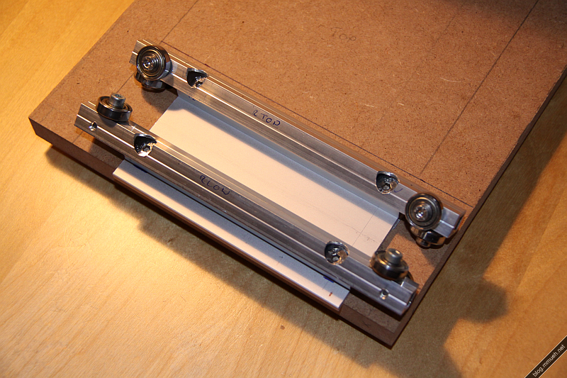
Here go the measurements. I use RMAA 5.5 free to do these.

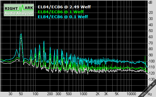
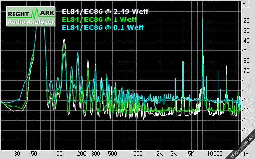
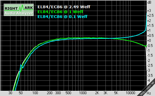
All measurements were taken off an 5R6 load resistor. The maximum output power reached at 1 kHz sine into 5.6 ohms was 2.49 Weff resp. 4.97 Wpk, which is right on the money. Soft-clipping occurs right above that. I am not yet satisfied with the rise above 20 kHz, which I suspect to originate from a missing bypass cap in parallel to the feedback resistor. The cap short-circuits the feedback resistor at high frequencies to prevent oscillation (which currently occurs at 30-50 kHz when the volume isn’t turned all the way to the max).

The 50 Hz spike, on the contrary, is lower than I expected as I didn’t bother placing the output transformers away from the power transformer or putting them at an angle to prevent the magnetic fields from interfering. Another of those times when function follows form. Shielding in the wiring compartment could be improved a bit, though. Dunno if I should really photograph this mess.

UPDATE: And here comes a screen of the schematic. No need to do it in EAGLE as there is no PCB, the whole amp is air-wired. Enjoy.

The usual word of warning: This circuit operates at voltage levels of >= 275 Vdc at relatively low supply impedance, so please be aware that you build this circuit at your own risk, and proceed with caution! I am not responsible for any damage/injury that might occur related to this circuit.

As I already mentioned, there are lots of parallels to the linked amps from the last post. A few annotations concerning the schematic:

  • C5 is still missing in my case, estimate by trial and error.
  • Some parts dissipate a noteable amount of power, as marked – choose for at least 2W of dissipation to be on the safe side. You might want to oversize a bit here, to minimize aging of the parts due to thermal stress.
  • The coupling caps C3,C4 should be designed to handle voltages > 300 Vdc at least.
  • R9 is the loudspeaker, of course ;-)

Another piece of advice I learned during testing: If the connected audio source device is somewhat valuable, it is wise to install a suppressor diode directly across the input in such a way that is shorts high potential at the input to ground. In case any high voltage potential gets through the capacitor in form of a spike (like it did through a damaged socket in my case), this will at least save your soundcard a lot of undue stress.

EL84/EC86 Tube amp

This is a project I started some 5 years ago. It is the first tube-amp I built (and the only one so far), but I made an error in the calculations back then which led to absolutely nasty sound. No lows, oscillation and unproportional hi-end. Need me to say why it was sitting on the shelf ever since?

Yesterday I redid the calculations, now that I think I have a better understanding of how tubes want to be treated – and this time around I was successful. The frequency plot needs yet to be done, but from listening I like it very much so far. The tubes are also no longer the original ones, it was originally equipped with two EL83 from TESLA and two EF860. The EF860 did an okay job as a preamp but was very microphonic – that is, picking up vibrations from the casing – whereas the EL83 simply can’t handle much anode dissipation power, about half that of the EL84. Output power was limited to just above 2 Wpk.

Some basic facts:

  • JJ EL 84 power pentode as output tube, single ended configuration
  • ORION EC 86 single-triode as preamp tube
  • 275V anode operating voltage
  • HSGM (german company) output transformers for EL84 SE
  • Total amplification preamp ~ 10-fold (optimized for consumer audio devices)
  • Global feedback including output transformers
  • Peak output power ~ 4 W
  • Beech wood & brushed aluminum casing
  • And the blue tape on the transformers is there to creep off anyone (me) thinking of accidentally sucking power off the transformer rails with his finger or other body parts while ogling it in the dark. This is not to become a permanent aesthetic feature, but there are no transformer caps available for this type. I will build something out of epoxide PCB, I guess.

I will put my schematic, the bode plot and exact part types up here in an extra post as soon as I get my scanner to work. Until then, I advise you to visit the following sources which helped me a lot and are always an inspiration for me. Dig through the news section, there are some GREAT projects.

  • Pentode SE amp using 5B/110M tubes (german reader’s project on Jogis Roehrenbude, my schematic has become very similar. Great explanation of the necessary calculations)

Seems like my biggest mistake in the past was not to account for the voltage drop over the output transformer, induced by the bias current. *facepalm* I totally forgot that.

See also: Second post, containing schematics & measurements…

Das Blog und der Server [DE]

Die Probleme zwischen diesem WordPress 3.1.3 hier und dem Telekomserver sind endlich gelöst!

Sieht so aus als war ich die ganze Zeit zu blind um zu bemerken, dass die Umstellung von PHP4 auf PHP5, die über eine .config-Datei möglich ist, für jeden Ordner getrennt passieren muss. Dasselbe gilt für jede Einstellung über eine php.ini – das gehört alles in den Hauptordner vom Blog, nicht das Wurzelverzeichnis vom Webspace. Und ich hab’ die ganze Zeit nicht bemerkt, dass im Hintergrund noch PHP4 werkelt.

Als Hinweis – bei mir traten folgende Symptome auf:

  • Uploads von Bildern laufen durch, danach steht aber beim Einbinden in einen Post oder eine Galerie nur die Größe “Full size (0 x 0)” zur Verfügung.
  • Schwierigkeiten bei verschiedenen Skripten und Plugins die PHP5 erwartet haben – logisch irgendwie. Speziell der Plugin-Updater schmiert ständig ab.
  • Sehr gehäufte Fehler wie

    PHP Fatal error: Allowed memory size of 33554432 bytes exhausted (tried to allocate 5275922 bytes) in /home/www/wp-includes/media.php on line 254

    in der entsprechenden Logdatei. Außerdem Hinweise auf versuchte Speichervergrößerungen durch WordPress, die verhindert wurden.

  • GZIP wehrt sich vehement gegen alle Versuche, das Blog etwas zu schrumpfen. Abhilfe schafft da ein kleiner Trick (siehe unten), aber da PHP4 aussterben sollte ist der eigentlich irrelevant. Mit PHP5 funktioniert jedenfalls jedes beliebige WP-Plugin dafür.

Mann, komme ich mir grade doof vor ;-) An bestimmten Tagen sieht man den Wald vor Bäumen nicht, und am Tag danach versteht man auffallend gut woher das Sprichwort kommt. Immerhin kann ich jetzt endlich die restlichen Designänderungen umsetzen, ohne dass mir seltsame Fehler gleich wieder einen Strich durch die Rechnung machen.

Dank geht hierbei speziell an faulthiel, der in seinem Blog eine ansehnliche Sammlung von Tipps und Tricks rund um WordPress bei der Telekom zusammengestellt hat.

Die Konfiguration vom Webspace verlangt am Ende zwar etwas mehr Aufmerksamkeit als anderswo, aber ansonsten läuft das Blog wie geschmiert.

Weitere Links zu passenden Themen:

“Erhöhung php memory limit?” im Telekomforum

“PHP.ini & memory_limit” im Telekomforum

“Gzip without gzip” auf dieser Seite

Workbench #1

LED driver again

The first version of the LED switching driver just exhaled a portion of magic smoke. The IC is neither the culprit nor the victim, there must have been a short somewhere else. The sense resistor was fried and acted as a fuse, but it wasn’t fast enough to prevent the current blowing another transistor on the motherboard that switches power to the backlight. Funny, didn’t even know there was such a thing. Maybe that explains the weird current shortages at the LED driver input that caused some of the flickering. The LT chip seems to have survived just fine, again.

Whoops, forgot to mention: Yes, it has been running ever since the last post about the topic ;-) so far, so good.

Anyways, gotta do this one again. To counter the problems with flickering, the new driver will run from 5V of the HDD/USB supply, operating in pure boost mode. Stepping from 5V to 9.6V will never cause it to even get near the crossover point where it would need to switch from boost to buck mode, and there will never be a lack of control range.

To explain that part, remember that the LT3518 runs in fixed frequency mode and varies only the pulse/pause ratio of the switch that draws power through the inductor. Let’s also assume we are in buck (stepdown) mode and the output current (LED current) is the variable the IC is trying to regulate. As the output voltage of a step-down converter is proportional to the on-time of the switch, the switch needs to be open all the time when the input voltage drops to or below the needed output voltage (that is, the voltage required to drive the desired LED current). Now, the LT3518 has a limitation in its pulse-duration caused by the design of its internal circuits, which in this case results in a maximum on-time of about 92%. If the required on-time rises above that, the IC can no longer guarantee proper function and instead of opening the switch permanently the regulating circuit begins to glitch, which results in flickering, low LED current and whatever else. It is not a danger for the LEDs though, because whatever happens, a step-up converter can never reach a voltage higher than its input.

I admit that I was kind of slacking off to assume it would work alright somehow – well, it didn’t ;-) Lesson learned, that’s why I don’t mind this happening. Sometimes doing it wrong is the only guarantee you’ll do it right the next time. The next version of the driver circuit will come with full eagle layouts and stuff; so please don’t get too hooked to the old design. It is only usable if you can guarantee a, let’s say, 2V surplus over the typical output voltage at the input all the time.

The new design will probably be done and up here ’til Sunday this week, and there will be some extra stuff with the CNC (stepper driver ICs arrived, some work on the axis’)