Now that a communication with the STM32 has been established, it’s time to start checking out the data exchange a bit more. From Jaro’s notes (see references in part 1), many of the most important IDs are known already. However, I suspect that there’s more to that. For example, it appears that the app can display the filtered air volume rate, which means that either the value itself or some kind of motor power or RPM value should be available. Looking at the ID scheme also brings to mind that there are a lot of spaces that can be filled between the known commands.
Continue readingFixing broken stuff
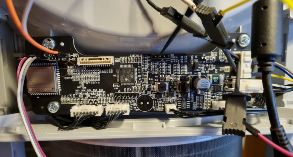
Improving a Xiaomi Air Purifier 3H (1)
I bought this used broken unit after covid, not really to solve any air problems but because I found the integrated sensors pretty interesting for the price. The Xiaomi air purifiers operate on a laser particle sensor to measure air quality, combined with a Sensirion SHT temperature/humidity sensor. The data are available over wifi via the smartphone app, which is rather not to my liking – especially hooking up such a reportedly unsafe ([4]) device to my network. That is something I wanted to change, along with fixing the motor. Well, a lot of time has passed, but now it’s actually happening.
I’ll try to add to the others’ knowledge wherever I can. I am currently writing my own custom software for the ESP32 with the aim of integrating the 3H into an MQTT ecosystem, but keeping out overhead like ESPHome or Home Assistant. I’ll push that to Github in the next few days when it’s finished – more to follow here. The code is written for the Espressif IDF toolchain, to be compiled in the Eclipse IDE. It uses standard libraries or openly available ones wherever possible, but also builds on Jaro’s code for the communications part. At a later point I also want to dabble at replacing the STM32 code. I should mention that this post series is not about dumping or modifying any original code or data, or about anything related to the cloud link, since all of that is most likely a waste of time. I’m not going to keep any linkage to the original cloud/app, but for the time being successively replace parts of the functionality – which requires me to figure out how things talk to each other.
Continue readingSamsung SSD resurrection
Yesterday, a discarded Samsung SD863 datacenter SSD found its way to my hands. Although a bit older – this one’s from 2016 – these are supposed to be quite reliable (except for a few rumoured firmware bugs), and 480GB of capacity are not to be disregarded even at today’s remarkable flash prices. Since it did not suffer from the usual drillholes of unreadability, I hooked it up to a linux machine – hopefully immune to virus-infected, supposedly “lost” thumbdrives – to give it a try. Unsurprisingly though, the drive announced 1GB of capacity, which does not fit its type MZ7KM480HAHP and explains its disposal. I had a hunch that the reason might lie with the microcode:
ata6.00: ATA-9: SAMSUNG MZ7KM480HAHP-00005, ERRORMOD, max UDMA/133
...
sd 5:0:0:0: [sdd] 1965352 512-byte logical blocks: (1.01 GB/960 MiB)
ERRORMOD as a version index looks rather like something went horribly wrong, causing some kind of corruption to the firmware. At least it still communicates through SATA, which indicates some backup capabilities.
Continue readingVOLVO 850: Broken speedometer
Recently, the speedometer of my trusty old Volvo 850 station-wagon started acting up. Initially, it would just drop to zero intermittently at speed, then come back. Hard to notice if you only so much as glance at it every now and then. Over the last two weeks this got worse such that it would only very rarely do anything at all. My best guess for the cause would have been the speed sensor at the vehicle underside, but for mysterious reasons the odometer was still going at the normal pace. According to the instrument schematics, this should not be possible if the sensor were broken – same signal for both. Continue reading
JAMO 660 subwoofer amp
A few weeks ago a friend brought me an old subwoofer that was discarded as broken – a JAMO SUB-660, which is an 600W sub for home cinema with integrated amping. The sub receives pretty good reviews, so I set out to try and fix it. I have worked on quite a few power amps until now, but as fully switched designs like this rarely fail, it is always a challenge when they do.

Schlumberger 4002: Overview
After quite some time, I am finally starting to check my 4002 signal generator in-depth. The first thing I want to do before really starting this project is to get a good idea of the system layout, hence the “part 0” thing above. I will link from here to the different components as I wriggle through the unit and check them. As there is no service documentation freely available, I will go deeper into critical parts of the circuit along the way.
This will also help me simplify things later when trying to figure out which line went where, if things go wrong.
Clock source (Decade stage)

Contained in the bottom RF block, consists of a styrofoam-encapsulated 10.000(00…) MHz oven-controlled precision oscillator and some clock distribution buffering. This part sources the main TTL clock which is also available on the backside ports as an instrument reference. The picture shows the whole top side of the module block, but the actual OCXO and distributor PCB are on the right.

There are three additional circuits in this module: The 10 MHz TTL buffering and switchover for external references, a 10.7 MHz IF generator (PLL+VCO+Mixer) and another phaselocked VCO for a derived widerange signal (49.3-70.7 MHz according to the marking) which is used to fine-tune the RF synthesis stage.
Schlumberger 4002 signal generator
While working up some extra circuits for the spectrum analyzer, I managed to pick up an old signal generator from eBay.
I heard a lot of positive things about the German (actually French origin, please look at comments below. Thanks to Rohit for pointing this out!) brand “Schlumberger” before, even though there is no relation to any personal experiences with their equipment. Seems like they also ran some kind of subcompany outfit called “Solartron” or “Enertec” which would today sound more than fishy, what with all those copycat-brands out there. But when an auction came up for a reasonable price I decided to go for it after some short research on the net.
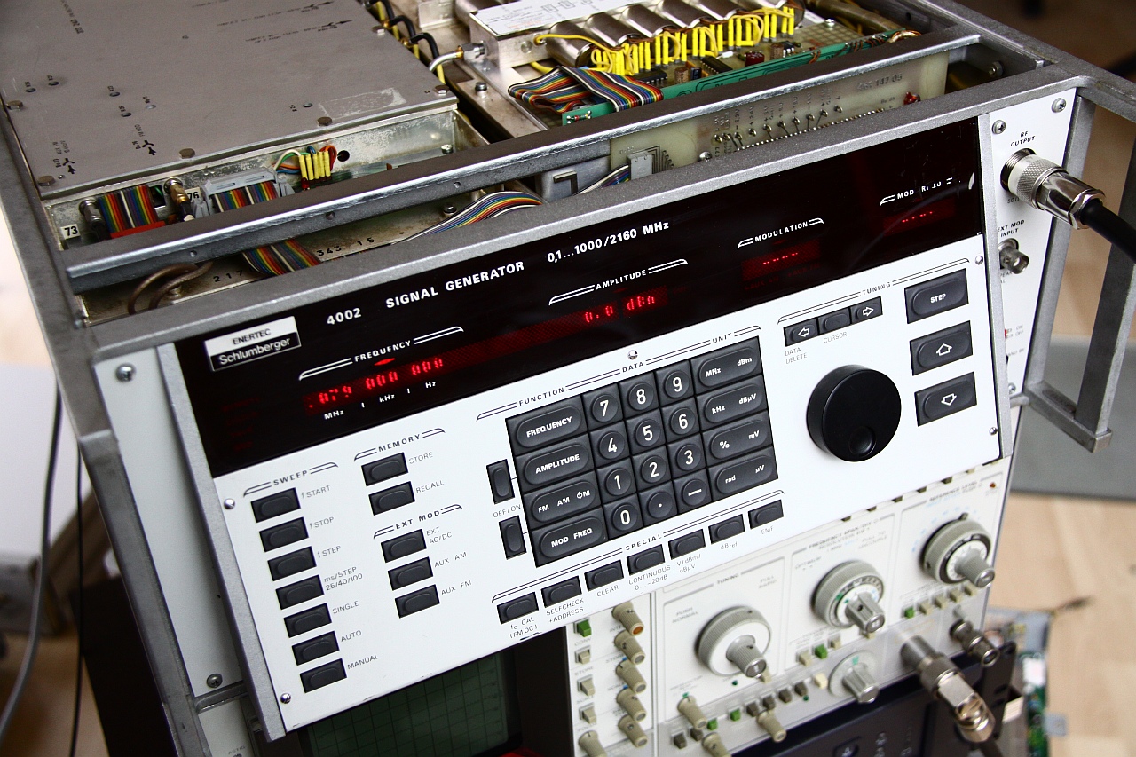
Don’t mind the tearing effect on the LED displays, not visible to the naked eye. I already pulled all the side panels.
What I got was a Schlumberger 4002 signal generator. It ranges from 0.1 to 2160 MHz with 10-20 Hz tuning accuracy, selectable output amplitude from -138.9 dBm up to +13 dBm in 0.1 dB steps, auto-sweeping and several extras like an OCXO for stability, 20 dB of linear attenuation range without using the step attenuator, an internal modulator and IEC bus remote control. If you looked at the photo closely, you will have noticed that the frequency range is written as “0.1…1000/2160 MHz” on the front panel. The reason for this is the optional doubler module included in this instrument. If the module is installed and detected, the software switches over to extended range without any further changes. Else, 1000 MHz is as far as it goes. More detailed specs will follow as soon as I can decypher the bad scan of a manual page that cropped up on Google. Judging from the inventory labels on the backside, the device must have been used in the manufacturer’s own lab. Unfortunately I have not yet managed to find any service info even though the manuals seem to be sold sometimes, for rather terrible prices. Continue reading
HP 8565A: Sweep time selector
As I already mentioned, the highest priority fix is the input RF attenuator. To get access to this, the control panel must be taken out since the connector is placed at a slightly inconvenient place – the bottom of the motherboard. Unfortunately, right beneath this is the aluminum carrier plate that contains all the RF circuits consisting of semi-rigid coax and clunky metal-jacketed modules. I first unmounted the top, bottom and right side panels, which was an easy job:
- Loosen the single screws at the back of top and bottom covers and pull them off towards the back.
- Remove the two screws holding the carrying handle and pull off the side panel along with it.
- Also remove the top and bottom plastic inlays from the front aluminum frame, these cover up the panel screws.
- Remove all visible screws from the top of the frame that seem to belong to the right panel (should be 3) and also from the bottom (should be 2). Take care not to remove the 2 rightmost screws on the bottom, these hold the front connectors and are best left in.
Now pull the control panel right out.

If it sticks, the points to watch out for are the N-type RF connector and the PCB edge of the sweep time selector. Gentle pulling while wiggling the panel up and down some will bring it out. Remove all connectors from the backside. Don’t worry, the plugs can’t be interchanged. Set the panel on a flat surface, front side down (Fig. 1). Continue reading
HP 8565A Spectrum Analyzer
Originally I was looking around a well known auction house for a digital Spectrum/Network analyzer from one of the older Tektronix 2715 or HP8566 series to extend my measurement rack to higher frequencies, but they are hard to find for a reasonable price in relation to the risk of buying a device in unknown condition. Still, I wanted one of the older models, because of their excellent design and repairability. Maybe without the exception for some very special, custom parts – but we’ll just hope that those don’t break.
Also, in my understanding a slightly older system from the top series at the time still outperforms most more expensive, modern, all-digital-hey-we-compensate-all-the-errors devices. That is not to say that digital processing and compensation of systematic errors is bogus, of course! But at the same time, any weak measurement hardware can be made to appear top-class by taking several thousand complete sequences and averaging. Getting it right on a single try is an art for itself, and designing a combination of precise hardware and just the right amount of post-processing is the reason for the price. Or maybe I’m just a sucker for retro tech, with all its edges, heavy metal and shiny parts.
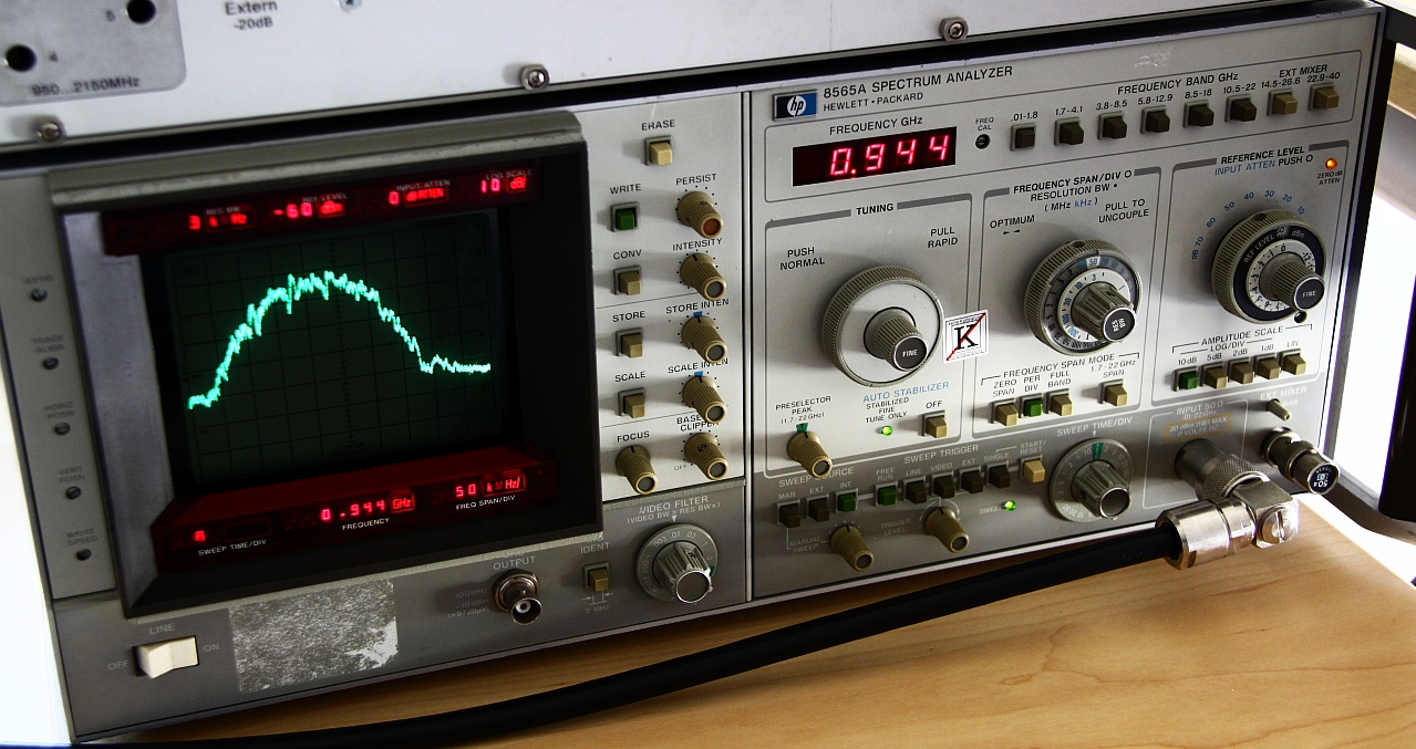
So, I finally got a fair deal on this 8565A unit. I might have wanted to choose its bigger brother 8569B instead, which has a wider external mixer span of up to 115 GHz and a digital control interface, but the LED readout certainly adds a special flavor to the set. The seller had informed me that the device would be uncalibrated and the sweep time selector didn’t work anymore. Usually such estimates contain some tolerance, so I already expected some other things that maybe nobody noticed. Since my original plan was to recalibrate whichever device I got anyway and fix all the problems over time, that would be okay. The fixes will be documented here. Continue reading
Sony TA-F220
These are just some short notes I took while inspecting an aged Sony TA-F220 amp some days ago. I have seen several of these over the last years, pretty decent amp with a nice sound. They all have some regular aging flaws in common, though.
