A few weeks ago a friend brought me an old subwoofer that was discarded as broken – a JAMO SUB-660, which is an 600W sub for home cinema with integrated amping. The sub receives pretty good reviews, so I set out to try and fix it. I have worked on quite a few power amps until now, but as fully switched designs like this rarely fail, it is always a challenge when they do.
Fig. 1: Jamo SUB-660 power amp module. High-power PSU (right top), standby PSU (right of centre), Class-D amp (above centre) with large output filter choke (centre). Preamp, sound filters and standby detector PCB on the left, line input on the bottom right.
These are just some short notes I took while inspecting an aged Sony TA-F220 amp some days ago. I have seen several of these over the last years, pretty decent amp with a nice sound. They all have some regular aging flaws in common, though.
So…it’s been a while. Somehow I thought, I’d have finished the CNC writeup by now, as well as my plans for continuing work on my plasma-bar meter project. Things turned out different.
I got into my Bachelor’s thesis after completing the preceding seminars, which kept me busy since june ’13. The topic is centered around signal power based speech DOA estimation using directional microphones, very interesting stuff from the domain of signals processing. I had a very interesting time learning lots of new things, and somehow I also wanted to get hands-on with the matter since attending several advanced DSP courses during the last two terms.
While working on the thesis, I realized that microphone array systems are really nice things to have to play around with. I decided to make my own, which I did in my free time in parallel to the thesis. Let me at least show some pictures as long as I still don’t get around to working on other stuff.
Whole array assembly.
Carrier construction for up to 8 microphones, spacing 25mm.
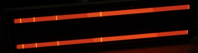
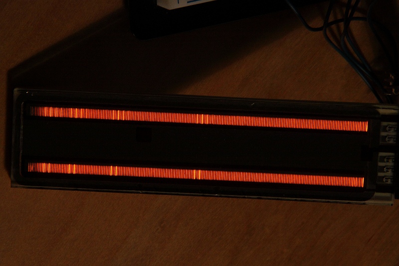
I picked up some unusual plasma displays from ebay some weeks ago, which I have been searching for quite some time now. The picture above shows an illuminated Burroughs PBG-12201 plasma bargraph display. They are pretty hard to get by now, and if available, prices are a real shocker. Some shops in the US that carry them ask for 230 USD and some even more. Sometimes they appear on ebay for about 50 USD, but you have to be real quick to get some. Best chances are with surplus stores that sell off leftover production stocks or disassembled devices that originally contained such tubes. A few very retro and very popular mixing consoles for audio applications used them as main VU meters (eg. made by Lexicon), as well as some current professional grade standalone meters (eg. RTW, one of those is where I first saw such a display and was absolutely fascinated by the deep orange hue). As they eventually get old and start flickering or burning in if not properly cared for, spare parts have become rare, and since Vishay – the most recent producer of these displays – has discontinued the product line in early 2012, I would expect the market to dry up even more.
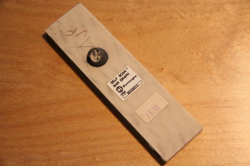
Back side with evacuation port
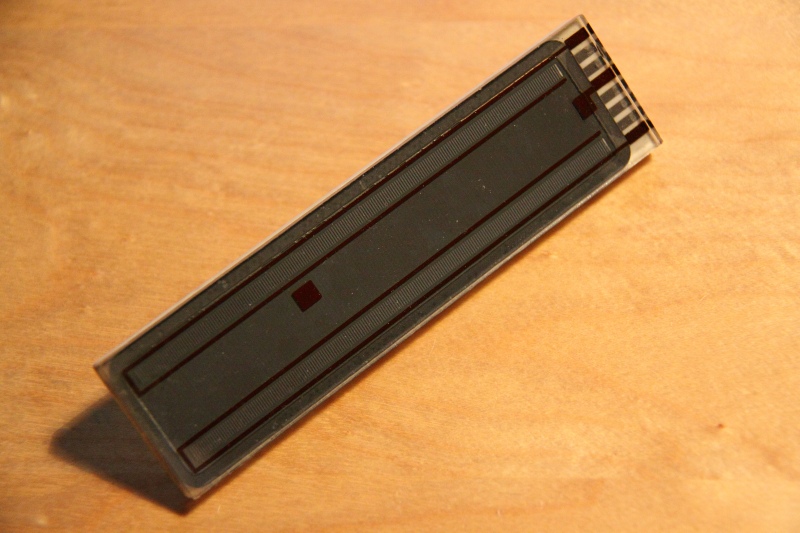
Burroughs PBG-12201
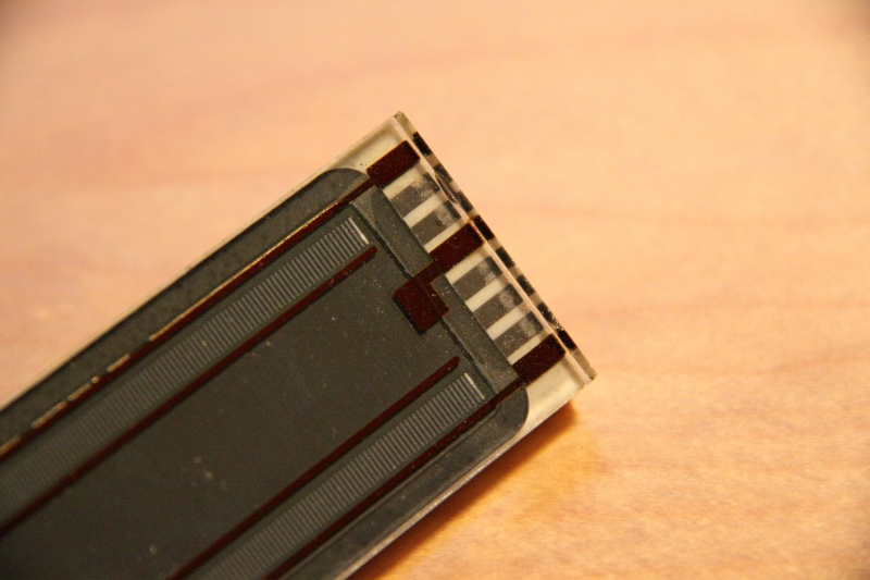
Closeup of contact strip
PBG12201 display with drive circuit
Tearing effect caused by the scan rate
Bar display with unsmoothed supply
Bar display with reservoir cap in HV circuit
Mine were obviously scavenged from some kind of device by a Hungarian ebay seller, he offered some 10+ pieces of the PBG-12201 type display for 8 Euros each – a real steal! I just couldn’t resist and got myself three of them, together with matching sockets. Thinking back, I don’t get why I ordered three instead of four…oh well, it’s done. The tubes show some signs of wear, like glass chipped off around the edges and burn marks on the cathode traces, but they all work fine. Continue reading →
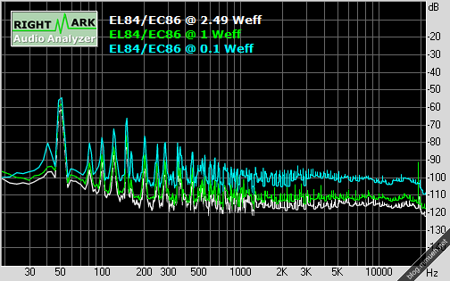
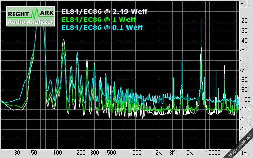
Here go the measurements. I use RMAA 5.5 free to do these.
EC86/EL84 Tube amp schematic
Total harmonic dist.
Noise
IMD+N sweep
Intermodulation+Noise
Dynamic range
Crosstalk
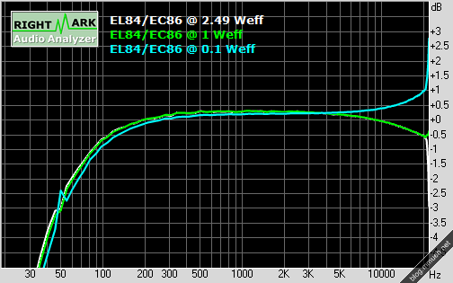
Freq. response
All measurements were taken off an 5R6 load resistor. The maximum output power reached at 1 kHz sine into 5.6 ohms was 2.49 Weff resp. 4.97 Wpk, which is right on the money. Soft-clipping occurs right above that. I am not yet satisfied with the rise above 20 kHz, which I suspect to originate from a missing bypass cap in parallel to the feedback resistor. The cap short-circuits the feedback resistor at high frequencies to prevent oscillation (which currently occurs at 30-50 kHz when the volume isn’t turned all the way to the max).
The 50 Hz spike, on the contrary, is lower than I expected as I didn’t bother placing the output transformers away from the power transformer or putting them at an angle to prevent the magnetic fields from interfering. Another of those times when function follows form. Shielding in the wiring compartment could be improved a bit, though. Dunno if I should really photograph this mess.
UPDATE: And here comes a screen of the schematic. No need to do it in EAGLE as there is no PCB, the whole amp is air-wired. Enjoy.
The usual word of warning: This circuit operates at voltage levels of >= 275 Vdc at relatively low supply impedance, so please be aware that you build this circuit at your own risk, and proceed with caution! I am not responsible for any damage/injury that might occur related to this circuit.
As I already mentioned, there are lots of parallels to the linked amps from the last post. A few annotations concerning the schematic:
C5 is still missing in my case, estimate by trial and error.
Some parts dissipate a noteable amount of power, as marked – choose for at least 2W of dissipation to be on the safe side. You might want to oversize a bit here, to minimize aging of the parts due to thermal stress.
The coupling caps C3,C4 should be designed to handle voltages > 300 Vdc at least.
R9 is the loudspeaker, of course ;-)
Another piece of advice I learned during testing: If the connected audio source device is somewhat valuable, it is wise to install a suppressor diode directly across the input in such a way that is shorts high potential at the input to ground. In case any high voltage potential gets through the capacitor in form of a spike (like it did through a damaged socket in my case), this will at least save your soundcard a lot of undue stress.
This is a project I started some 5 years ago. It is the first tube-amp I built (and the only one so far), but I made an error in the calculations back then which led to absolutely nasty sound. No lows, oscillation and unproportional hi-end. Need me to say why it was sitting on the shelf ever since?
Yesterday I redid the calculations, now that I think I have a better understanding of how tubes want to be treated – and this time around I was successful. The frequency plot needs yet to be done, but from listening I like it very much so far. The tubes are also no longer the original ones, it was originally equipped with two EL83 from TESLA and two EF860. The EF860 did an okay job as a preamp but was very microphonic – that is, picking up vibrations from the casing – whereas the EL83 simply can’t handle much anode dissipation power, about half that of the EL84. Output power was limited to just above 2 Wpk.
Some basic facts:
JJ EL 84 power pentode as output tube, single ended configuration
ORION EC 86 single-triode as preamp tube
275V anode operating voltage
HSGM (german company) output transformers for EL84 SE
Total amplification preamp ~ 10-fold (optimized for consumer audio devices)
Global feedback including output transformers
Peak output power ~ 4 W
Beech wood & brushed aluminum casing
And the blue tape on the transformers is there to creep off anyone (me) thinking of accidentally sucking power off the transformer rails with his finger or other body parts while ogling it in the dark. This is not to become a permanent aesthetic feature, but there are no transformer caps available for this type. I will build something out of epoxide PCB, I guess.
I will put my schematic, the bode plot and exact part types up here in an extra post as soon as I get my scanner to work. Until then, I advise you to visit the following sources which helped me a lot and are always an inspiration for me. Dig through the news section, there are some GREAT projects.
Pentode SE amp using 5B/110M tubes (german reader’s project on Jogis Roehrenbude, my schematic has become very similar. Great explanation of the necessary calculations)
Seems like my biggest mistake in the past was not to account for the voltage drop over the output transformer, induced by the bias current. *facepalm* I totally forgot that.