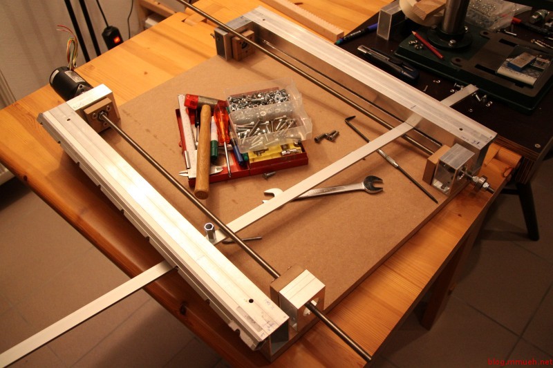
The CNC mill got into a working state right before christmas eve. I know it’s not a present in that sense, but still! :3
Some parts of it are still fixed with a lot of glue and tape (or zip-ties ^^), but for now that’s perfectly sufficient. Right now. it can already mill hard wood and MDF, so I will be redoing some critical parts that lack in precision and/or quality before I write up the whole project as one. Unfortunately, I fear that the original plan about using an (older) EPIA 800 board as a controller can not be followed, EMC2 just refuses to start on that thing. Grrrr…
More pictures and text will follow in a few day’s time. Until then, enjoy the holidays and have a nice and safe start into the new year!
Oh, right, and two Stellaris Launchpad eval-kits from TI that I ordered back in September arrived JUST ON the 24th. How great of a timing is that? I don’t care about the wait, it was well worth it and I knew up front – but thanks again to the girls and guys of the TI support, for solving all the technical difficulties along the way :-)
Work on the CNC continues…the end draws nearer. I am currently disassembling the whole thing as far as necessary to clean up all the edges and burrs and fix the positions of the parts relative to each other using hammered-in stainless steel pins. After that, it is just coupling the threaded rods to the moving parts and bring the stepper drivers alive.
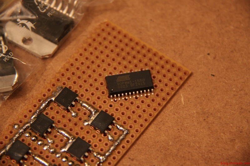
So much for the current status of the CNC milling machine. I have made some first experiments with L297/298 motor drivers and found out the hard way that these are quite overloaded with such strong motors. Burnt out in a matter of seconds. But, as BJT driver bridges are not state of the art anyways, and I want to take a lesson from this project, I decided to finally get myself some of those specialized ATMEL controllers (AT90PWM1) and try to design my own FET bridge driver.
I even have one in spare that I can use for experiments with a self-designed high intensity discharge lamp driver – I have attached an image of an early prototype to the gallery for your entertainment. Worked quite well for some time, but the driving was very crude – there are some logic gates on the bottom of that small pcb that generate half-bridge signals for the two FETs, but no care taken about anti-shoot-through and so on. VERY crude. I will report how well the new controllers work out, seeing that very few experiences are found :-)
As for the CNC, I am quite confident that I will finish the mechanics part within the next holidays (around easter). Then, all that remains is the ‘intelligent’ part.
Last but not least, I notice that I still do not manage to describe my projects in my self-desired level of detail. Thus I will focus more on taking pictures during the process and explaining from now on.
Alright, time for another update linked to the CNC mill! I just finished the linear carriage for the X-direction. Still having some minor trouble getting a tight fit between the bearing-rollers and the rails, but I suspect this will be correctable later through adjustment. The whole thing needs to be carefully calibrated and aligned anyways before real milling action is anywhere near possible.
To be honest, I don’t think the alignment of the parts will keep up with vibration and forces for too long, which is why the most crucial parts will be remade with this mill while it works – that was the goal from the beginning.
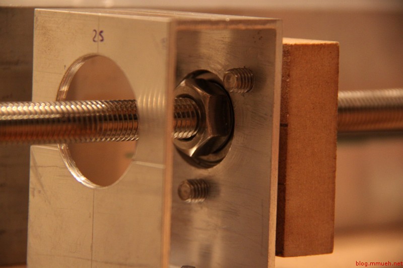
The next step now is to connect the threaded rod to the carriage and to finish the drive system for the Y-direction, which will reside below the table and pull the whole portal sled through a rod that passed through the table. The table supports and Y-rails are still sitting in the workshop, waiting to be cleaned up.
I remade the linear bearing sleds today, the previous ones were not precise enough – they were only the proof of concept anyway. The new ones glide on the rails as if they were not touching at all, VERY nice feeling if you lean on the bridge support with approx. 10 kg and slide it back and forth. No bumps, just smooooooooth metal! No clue how precise they are in terms of height differences and imprefections though, but there is a little potential to adjust if something should be too far off.
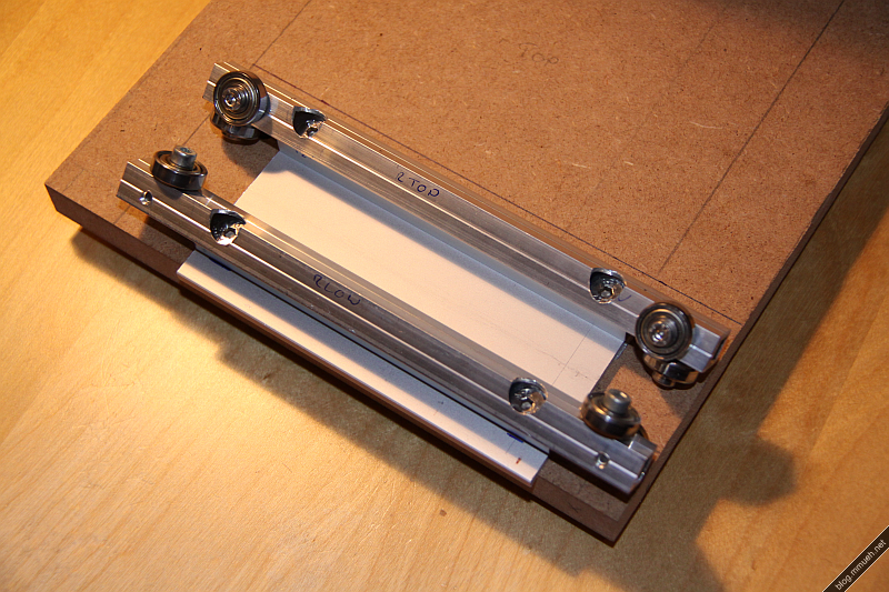
Whole construction so far
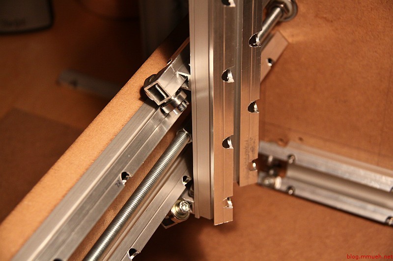
Portal supports with old bridge installed
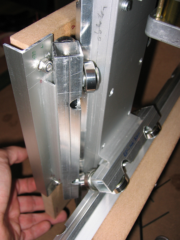
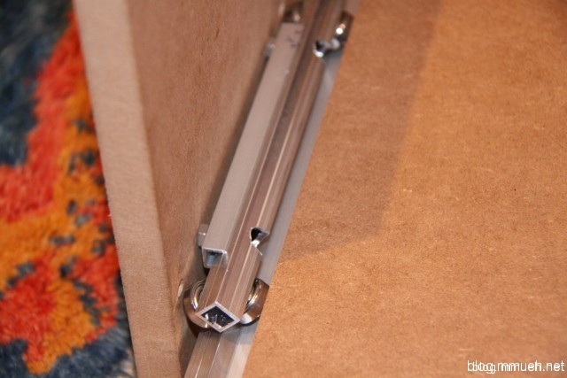
DIY linear bearing, side view
Linear bearing, first attempt
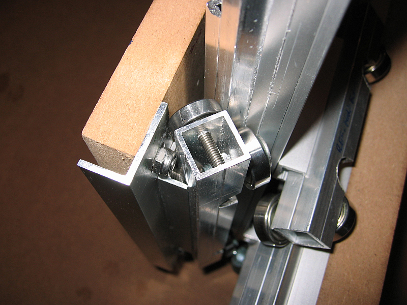
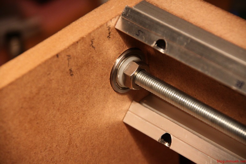
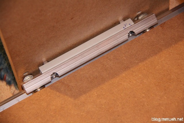
Right linear bearing, front view
Left linear bearing, front view
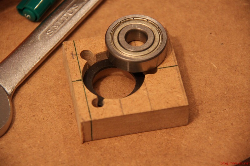
Parts for the linear assembly
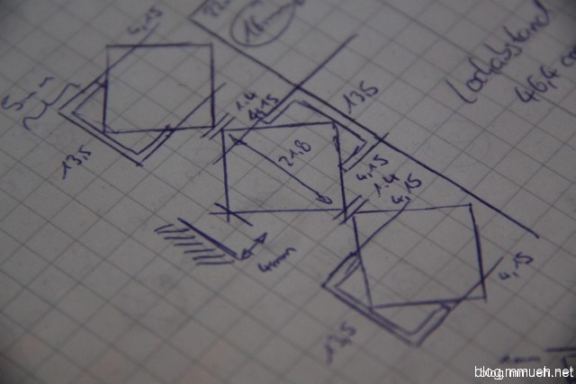
Cross-section drawing of rail assy.
The portal looks very good so far! BUT….the cross-bar is skewed -.- Not by much, only one or two degrees around the length-axis, but it is enough for the right bearing sled to not sit on the rail properly. I can force it on, of course, but that is not the great idea here as the sleds should fit snugly on the rails without any force besides its own weight applied. In the beginning MDF was planned for this part, but I settled for beech wood instead. Best option here is to dump the current one, buy a precise MDF cut tomorrow and stuff the beech back into the scraps box for some future case build. After that, if the dimensions and angles of the portal as a whole are within tolerances, two more bearing sleds are needed to keep the portal on the rails while moving and when milling action occurs. Two more of the exact same type should suffice, but maybe some kind of spring-loaded mount would be better for long-term stability.
The side supports of the portal will be redone after the mill is completed. As will some other parts, probably. I will have access to a cnc mill then, so why not do the holes and cut-outs a little more precise ;-)
Alright, so I finally decided what I want to do as kind of a long-term project in the coming time: A CNC mill which will get heavy use in the fabrication of PCBs, faceplates and enclosures. My case-building skills plain suck, so this nifty device will be helping me in the future. Also, this is my first real all-out mechanical build – meaning no straight way to the goal. In the end, it will probably have become a lot more expensive than I currently still hope for, but we’ll see about that ;-). (Account the extra expenses to learning and refilling the scrap parts box, distracts the wallet from groaning somewhere in a dark corner. Works most of the time.)
Sketchup of cnc mill
As I already wrote above, the main tasks for the machine will be PCB milling and drilling, machining wood, acrylic, plastics and aluminum. Maybe copper, and in the far future I want to take a shot at some steel sheeting, but all that is off the radar right now. I will try to aim for high precision and adequate stability. A portal mill seemed like a good idea at the time, especially because a moving table makes the machine just so much bigger while the workpiece must stay within relatively modest dimensions. I played with the thought for a while but then dropped it in favor of this design.
The whole thing will be controlled by linux-EMC or Mach3, maybe I can even fit a small EPIA-800 mainboard as a control computer in there if the drive mechanism allows enough leftover space. The controller will be custom made, mainly for education purposes on my side.
First, I did a draft in SketchUp to get a feel for the problems and dimensions, though it is already outdated by now. I will update it in the next days when I need exact measurements of the whole device again. Right now pen, paper and calipers are sufficient. The materials are almost all bought at the local hardware store, MDF sheets, V2A screws and aluminum parts in standard sizes. Fortunately they do have a decent free cutting service whose operators hit the measures on the tenth of a millimetre (or up until now, at least). Saves me some of the work.
Construction began with the machine table, which is a solid piece of 22mm thick MDF wood, 500 x 600 mm in dimension (long side along rails). The sheet will be reinforced with aluminum from below so it doesn’t bend or skew, but first the drive mechanics and electronics compartment below the table need to be done. Just as a side note, the milling area will be somewhere around 450 x 450 mm but that number is not final. I have noticed that some more changes to table and X-axis construction might be necessary and those will of course change the useable space on the table.
Table construction
Machine table:
The table is carried by two 67 x 35 x 2.5 mm aluminum rectangular tubing. The tubing also supports the linear rails which are self-constructed and still need to prove their usefulness. The first rail is already installed (see pictures), the running sleds are in preparation (still need some standoffs) and the portal flanks are halfway done.
Linear rails
Linear bearings:
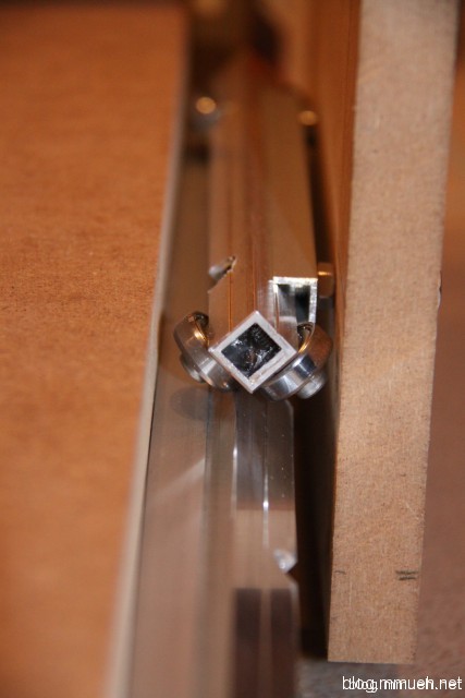
Made from 15.5 x 15.5 x 1.5 mm aluminum tubing with a slight groove in the exact center of each side, running along the length. The other part is a C-rail that fits exactly into this groove and supports the tubing nicely, giving it an exact 45° angle but believe me is a HELL to drill, even with a drill press. The carriage sleds of the portal consist of another 45°-rotated piece of the same tubing with ball bearings mounted to its sides in a way that they stand at 45° angles on the surfaces near the upper and lower edge of the rail. I have no picture of this part, will get some later today after I get around to reassembling the carriages.
The second rail is still in the making, will probably be finished today or tomorrow. I’ll try to get more pictures of the process but holding a camera while drilling seems not all that fun.
Stepper motors
A small teaser:
The stepping motors I got for quite a bargain, pretty powerful with around 1.85Nm holding torque. These beauties weigh in at 1.4 kg per piece, measure about 100 x 56 x 56 mm, sport a 6mm diameter shaft and survived the whole shipping torture without stuffing material or bubble wrap (YES seriously, who in his right mind ships 5 x 1.4 kg worth of steel and copper unwrapped in some otherwise empty cardboard box?!?) without even a slight dent in the shafts. The faceplate got a bit banged though, but nothing that can’t be polished up.
The drivers for these will be of my own making, probably AVR-controlled MOSFET fullbridge circuits. Half-stepping is planned, but I have not yet decided on microstepping. I guess that will be added if necessary for precision.
So long, stand by for more :-)
EDIT: Just noticed that this wordpress blog seems to distort my pictures if they open in the lightbox. Will see if I can fix that, must be something wrong with the script.
EDIT: Fixed, seems like some unwanted css found its way into the template.