Anyone who has already tried to use some kind of tablet device for writing should know that there are fundamental differences between screen types.
The most common is the capacitive type, where you use a finger or some kind of conductive pen to write on a glass surface, while the touchscreen device captures movement of the capacitance change through a grid of transparent electrodes on the backside of the glass. This works, but it sucks for writing precise text or drawing sketches. You can find these screens in almost every modern smart phone, tablet PC or kitchen appliance. They are cheap!
Next is the resistive touchscreen, where a small, hard point presses down on a plastic surface. The touch element is composed of two pieces of clear foil, coated with a conductive material. While the two layers stay isolated when there is no pressure applied, the pen forces them together in a certain point, forming a conductive path. By knowing the specific resistance of the surface coating, the circuit can determine the position of the pen tip by measuring path resistance from different edges of the screen. This type was pretty popular in PDAs (which have by now been fully replaced by smart phones, what a shame ;-) ) as well as the almost equivalent navigation assistants – and is not that common anymore. Writing performance is fair but not exceptional, though.
The third kind is the most interesting one. Real tablet PCs (the ones with the flip-over display) have this normal-looking pen with the nylon tip, which you can use to accurately write on the glass/plastic display surface. Many even feature some buttons on the pen, some kind of eraser on the backside – and they are damned accurate! They have another thing in common: Most of them use technology by a company called Wacom, also producer of digital writing and drawing pads for artists.
This type is called a “digitizer screen”, and it uses a sensing panel *behind* the actual display to recognize and track the pen. The digitizer panel contains an amazing set of surface coils to provide an alternating magnetic field through the screen. Inside the pen, there is a resonant circuit which uses the field energy to transmit the button states and even pressure on the pen tip back to the coil. By monitoring the strength of the resonance through different surface coils, the digitizer then calculates the position of the pen above the surface. In other words, you get a high-res info about the pen position (easily above 25.000 points resolution along the surface edge, depending on the digitizer type!), you know the pressure applied, button presses on the pen and even where the pen is when it is not yet touching the surface.
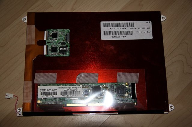
I recently disassembled a trashed tablet PC (Toshiba Portege) with a broken motherboard for interesting parts, and came across this:

The LCD panel is a LTM12C328T type. Attached to the backside is a SU-010-X01 tablet pen digitizer, and the marking on the ICs clearly suggests that it is made by Wacom. This would make a fine graphics tablet – but how to attach it to any other PC?
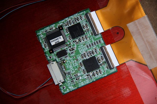
Further examination shows two Wacom ASICs (W8001) and a board number (PWB-A542-X). No pin markings, though. And, as usual, no datasheets available.

The digitizer was connected to the original mainboard through this 14 pin connector (pin 1 on the top end). All wires end at the LVDS display connector on the motherboard, which is the singular connector for all display-related components in this tablet device. No pinout information is available, however – except for some speculation on the internet.
What we have is: 14 pins total, 3 wired red (1, 13,14), 7 wired blue (6 through 12) and 4 unconnected (2 through 5). I already removed the original wires when I took the pictures, sorry!
From the coloring of the cables it is pretty obvious, that some are different. My assumption about the red ones being power while the blue ones carry data can be confirmed by analyzing the layout of the interface PCB. Pin 14 attaches to the large ground plane – ok. 13 leads through some SMD parts, probably coils, to two different paths, decoupled by capacitors. Probably VCC, ok. The voltage is unknown however, so I just assumed it to be either 3.3V or 5V. Any higher stabilized voltage is uncommon for this type of circuit.
That leaves pin 1, which is also colored red. This one leads directly to the interface chip, but there is a solder bridge (open), which connects it to the GND plane – which makes it GND, but probably some kind of semi-isolated GND for the interface. I closed the solder bridge to nail this to ground. Then I applied 3.3V from my lab supply to the board and probed all remaining pins with the scope.
The first thing I found was that there is no data activity going on with the pen away from the display. In this case, all pins are low except for #12, which has an on-board pullup resistor of 22 kOhms. Maybe some kind of reset signal.
When the pen gets near the display, stuff happens. While it is still a short distance from the surface (even through 15mm of wood table!), pin #6 jumps to high. At the same time, a continuous data stream appears on pin 9. No other activity can be detected though, so I suspect a serial interface. If the pen touches the surface and pressure is applied to the tip, pin 5 also goes high. By now I know that this was only a lucky coincidence, because the panel not necessarily transmits stylus position data right away.
That brings me to a preliminary pinout:
- GND (logic)
- ?
- ?
- ?
- TOUCH (active high)
- PRESENT (active high)
- ?
- ?
- (Serial?) TX
- ?
- ?
- RESET?
- VCC (3V3)
- GND (common)
Another assumption needs to be made about the serial interface. First, a back channel is likely to exist, as the PC can usually query the tablet for parameters. This can be deduced from linux Wacom device drivers for the W8001 chipset. Also, the typical baud rate for serial tablets seems to be 19200 or 38400. I am not sure, however, if the tablet supports any type of flow control. The extra connected pins suggest that at least two such lines exist (probably DTR/RTS), but the scope shows no activity.
Now I connected the panel to my linux PC through a MAX232 IC and a cheap Prolific PL2301 serial-USB converter. Pin #9 goes to the PC RX, and I tried pin #10 as PC TX, because the pair #7/8 somehow seemed much more probable to be flow control lines by layout. Next, I managed to find out something about the serial protocol. There appear to be several, which are quite well documented. I guessed the panel to be of the ISD V4 type, because it was previously connected to an ACPI internal serial port – so, ISD probably stands for “Internal Serial Device” or something like that. These devices feature a reduced command set without any response to presence detection, which means that no auto detect is possible and it therefore won’t work with Windows – even if you use tricks like editing the registry for serial tablet detection. The driver needs to KNOW that a panel of this type is present, and where it is. Wacom had a special driver for such tablets, but it is no longer available.
Care has to be taken with the MAX232 though. The panel seems to be 5V-tolerant, but I did not want to take chances. I dropped the MAX232 supply voltage as far down as possible, which is around 4.5V. Depending on the components used, that may or may not work. A proper USB/3.3V serial coverter is the correct choice.
More info about the protocol:
http://sourceforge.net/apps/mediawiki/linuxwacom/index.php?title=Wacom_Protocol_Overview
Using a serial terminal, I set the port to 38400 baud and tried to send the ASCII “*” character, which queries the stylus info. No response. The same happened on 19200 baud. This is not surprising though, because the panel only responds to “*” if it is in the stopped mode, so a “0” (zero) has to be sent first. I found that out by probing around on different baud rates and combinations. Finally, the panel responded with 10-byte sequences and could also be switched to stylus streaming mode.
At this point I tried to hook the archlinux XServer onto the device. After installing xf86-input-wacom, I created a new config file in /etc/X11/xorg.conf.d which I named 99-wacom-isd.conf:
1 2 3 4 5 6 7 8 9 10 11 12 13 14 15 16 | Section "InputDevice" Identifier "WACOM ISDV4 stylus" Driver "wacom" Option "Device" "/dev/ttyUSB0" Option "Type" "stylus" Option "Button2" "3" Option "AutoServerLayout" "on" EndSection Section "InputDevice" Identifier "WACOM ISDV4 eraser" Driver "wacom" Option "Device" "/dev/ttyUSB0" Option "Type" "eraser" Option "AutoServerLayout" "on" EndSection |
This tells X to try and add this tablet, whenever a new hardware device is plugged in. Note that it does not use a device class, because the tablet will not broadcast its type! After a reboot, the tablet is recognized by default and usable as a pointing and drawing device. If it does not work, chances are that the panel requires a reset (read on below) or that the serial port is not setup correctly (should be 19200-8-N-1, no flow control). This leaves a final pinout (highlighted are all pins used in simplified operation):
- GND (logic, can be shorted to common by solder bridge)
- ?
- ?
- ?
- TOUCH (active high)
- PRESENT (active high)
- Flow control (?)
- Flow control (?)
- Serial TTL TX
- Serial TTL RX
- ?
- RESET (?)
- VCC (3V3)
- GND (common)
Some questions are left:
- Is there flow control? What about pins #7,8,11?
- How is the reset handled? Often the tablet will not react to serial commands after power-up and will therefore not interact with the driver. In this case, pin #12 needs to be pulsed low to make it work. It appears as if there is no internal power on reset circuit, so this was probably triggered by the tablet driver after booting.
- What about the pins #2-5? Some devices seem to have an USB port on these, but mine does neither have any kind of pullup on these pins (needed to select USB speed) nor does it react to applying a USB bus.
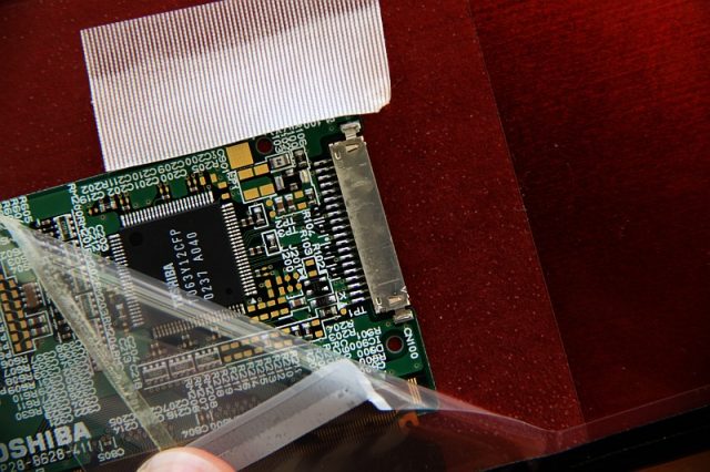
Now, all that is missing to my very own LCD graphics tablet is the LCD part. Panelook.cn tells me that it is a Toshiba 12.1″ 1024×768 TFT display with CCFL backlight, but again – no datasheet. The interface is probably LVDS, judging from the cables and mainboard trace layout. I still have one of these VGA-LVDS converters laying around, so I will use it for this project. There is also a model with DVI in, to which I will upgrade later on – or replace the panel, something like that.

What is missing is – again – the pinout for the 20 pin panel connector. From examining the panel input header and measuring conductivity, I decided on the following layout:
- VCC 3.3V (red)
- VCC 3.3V (red)
- GND (red)
- GND (red)
- LVDS O0- (blue)
- LVDS O0+ (white)
- GND (red)
- LVDS O1- (blue)
- LVDS O1+ (white)
- GND (red)
- LVDS O2- (blue)
- LVDS O2+ (white)
- GND (red)
- LVDS O3- (blue)
- LVDS O3+ (white)
- GND (blue, to shielding)
- N/C
- N/C
- GND (blue, to shielding)
- Unknown signal (blue, to shielding)
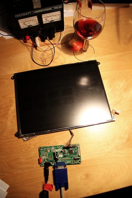
This layout is pretty much the standard LVDS header layout, with the ground lines in between and all, so I am pretty confident with this. As for the data format, this can be guessed: 1024×768 is obviously the resolution, and color depth is usually 6 bit if we are talking about a portable screen. 8bit are only common in desktop displays. The converter needs to be jumpered to these values. And – after hooking the panel up to the LVDS converter – it works like a charm!

A little hard to see, but we have picture! This needed some wine until it worked…and the backlight is not yet plugged in.
Finally, a little calibration is needed on the software side to fix the digitizer mapping to the screen surface (xsetwacom) and the DIY paperless scratchpad is finished! Well, it still needs a case of some kind, but some CNC work will fix that.
Appendix:
- Calibration:
#!/bin/bash
# WACOM SU-010-X01 calibration data

xsetwacom --set "WACOM ISDV4 stylus" area 0 0 24000 18300
This script needs to be run after attaching the tablet. It tells the driver to map pixel position 24.000 in X direction (right border of tablet) to the right border of the screen, and the same for the vertical axis. All values are approximated by trial and error, but they fit pretty well. Note that the aspect ratio of your configured active area should be the same as that of the screen, so you may lose some space if you want to write on a (extra) widescreen display or else the drawing might be squeezed slightly. If the attached display is used, everything is fine.
- Backlight:

Fig. 5: Testing the digitizer some. Turns out the display is a piece of junk, bad colors and low resolution. The Wacom panel is sooo much better! Again, this time with the backlight enabled. The display is not the best in terms of contrast, I will try to get my hands on a Lenovo X230 IPS tablet screen. In the meantime, it is sufficient as a secondary display. Even though the writing looks kind of crude from the picture, the digitizer picks up every last nuance of the pen movement.
By the way, the CCFL inverter is a special type. It uses a piezoelectric transformer instead of a standard magnetic one, probably to avoid emissions near the digitizer. Its pinout is #1/2=VCC (>=5V), #3/4=GND, #5=Dimming (connect to VCC), #6 unknown, #7 unknown
I came across this post while trying to google for the same purpose. Got a dead laptop (Acer Travelmate C300) with a good Wacom screen. My screen seems to use the same chips (googling the part number is what brought me here) but I’ve got a (maybe) big benefit. This one has labeled test points. https://cdn.discordapp.com/attachments/314400933486264320/535806053149835264/20190118_235930.jpg I don’t know what they all correspond to but I get the obvious ones. I’ve gone and lost my multimeter so can’t test what points goto which wires yet.
I’m hoping to get mine working on some version of windows with the original drivers since my programming and linux skill is basically 0.
Hopefully you’re still keeping watch here so you can make any use of this info and maybe helping me pin it out so I can wire mine up properly.
you are my angel, helpt me a lot
Hello, I went through all this many times, with many people. Wacom digitizer boards varies quite a lot. Some are USB, some are Serial. For interfacing it, there are multiple choices, including a little more hardware. Althought the forum is quite vast and is difficult to dig, there are some helpful info in there and the waxbee project that might be of help.
http://forum.bongofish.co.uk
http://wiki.bongofish.co.uk/doku.php?id=bongofish:penenabledhttp://forum.bongofish.co.uk/index.php?board=25.0
Hi Bernard,
thanks for stopping by! I already stumbled across your projects some time ago and poked through the waxbee sources – nice work, by the way! :-) It’s on my long-term todo list, especially since the linux wacom ISDV4 driver seems to be getting worse. Autodetection is pretty much broken right now.
Good afternoon! probably. I had the same problem with function display with digitizer from HP TC1100 to my computer. But slightly different circuit controller. Could you draw a diagram to connect chips from the display to a desktop computer.
PS driver software installed without any problems via rs232?
Hi Aleksandr,
sorry for the late answer, I was buried in work in the last weeks. I also got your e-mail.
Connecting any serial wacom tablet directly to RS232 is problematic because of the incompatible logic levels. You will need at least an MAX232-IC in between. As a sample schematic, have a look at the TI datasheet (http://www.ti.com/lit/ds/symlink/max232.pdf) on page 10, section 10.2.
Connect like this:
Tablet TX -> MAX #10 —> MAX #7 -> RS232 RX
Tablet RX <- MAX #9 <--- MAX #8 <- RS232 TX Plus the tablet supply lines (5V and GND). As I don't know your tablet module type, I can't guarantee that the pinout given above in the original article is identical. I would suggest you buy a cheap USB/Serial TTL converter and use that, you can connect the tablet signals directly to the serial side this way. Regarding your mail, I have not managed to install the tablet under Windows 7 and above. Only Linux so far. It might be possible under Windows XP (see third comment in the thread below, written by me, paragraph #3. You can find appropriate drivers on the wacom.eu page, but I cannot test if they work since I don't run any XP machines anymore.
Thank you very much for your answer. There was also loaded with work. :)
TTL converter I bought. Even in the summer. I’ll try to finish in the near future.
I have this same hardware and would like to use it in a similar setup. I have all the original parts from this tablet PC, if that’s any help. I have limited electronics experience, but I can write software for this if necessary. I would like to use it with Windows and I have a few questions.
1. Is this digitizer capable of reporting a range of pressures or just touching/not? Were you able to get this working with your setup?
2. I understand the Wacom controller must have the bold pins connected to a serial port, but what about the other pins?
3. Would Wacom likely have a Windows driver for this or would I have to develop my own? I don’t think I had to install drivers when this system was working.
Your blog post was very detailed and I’m glad I don’t have to start from scratch. Thanks!
I plan to pick up an LVDS controller board from eBay, by the way.
Hi Kristaps,
first, thanks for reading :-) I’ll answer your questions in order:
1. Yes, it does sense pressure, but I can only guess at the number of discrete steps. From my tests and several pieces of info from the web, 256 seems to be a realistic number that is common for tablet screens (and VERY sufficient for writing and drawing). The drawing software must be capable to use the info though. I mostly use Xournal in linux, but under Windows any application that allows tablet input will do fine.
2. For this type of digitizer, the non-bold pins can be ignored. Some are intended for extra features like a blinky “pen is on the tablet” LED or such, and maybe advanced serial port usage. Just leave them unconnected, you will not lose features by that. It is however important to attach both GND connections (tie together) AND to take care of the reset pin. This piece of info has not yet made it into the article above. The problem is that the panel does not always become active by itself when power is applied. I solved this by soldering a small 100nF cap (ceramics or foil will do) between the RESET and the nearest GND pin. This has the effect that in the turn-on moment when the capacitor is uncharged, a short low pulse is applied to the RESET pin, which suffices to start the circuit correctly.
If you want to avoid the electronics part, you could also send this pulse from the PC using one of the signal lines of the serial port, like DTR/RTS. Just set it low for a short (uncritical) time, then keep it high during operation.
And finally, you might want to worry about the signal levels at your serial port. Standard RS232 uses pretty high voltages which this panel might not tolerate, because it works with 3.3-5 volts. Unfortunately, this is not anything you can remove from the original mainboard. You can try to use an USB to serial converter for this since they mostly also only deliver 5V at their pins. As described in the article, I use a little single-IC circuit to fiddle with the logic levels, for which I could provide you the schematic if that helps you any further. I will also do a test if the panel can be made to work without this (only with a USB/serial adapter), say, the next weekend.
3. Yes, at least they had, and they were usually pre-installed in Windows Tablet. I tested several versions which are said to have worked for such panels until Win XP or so, but none of them would run in 7 and up. Either they crash or don’t react to the tablet at all, probably because of the castrated serial support in the newer OSs. If you want to give it a try using XP, check the WACOM page (wacom.eu), look under “Support”, “Drivers”, then enter Windows XP as the OS and “Tablet PC” as type. You are looking for stuff that supports “penabled” systems, and you might want to give different driver ages a shot because WACOM changed something with the structure in between somewhere. Meaning, the older one might actually work better.
As for the LVDS controller, anything should be fine. There are lots of them out there. I can still remember the times when people in electronics and PC modding forums would tell anyone off who dared to ask about “reusing an old notebook LCD panel”. Nice to see that this is finally well over ;-)
For any self-developed driver, maybe this info on the serial protocol can help you further:
http://linuxwacom.sourceforge.net/wiki/index.php?title=ISDV4_Protocol&action=edit
Good luck on your attempt, and feel free to ask if anything comes up!
Thanks for the quick reply. My current machines all use Windows 8+, so drivers may indeed be an issue. I’m a little short on time at the moment but this looks like a pretty straightforward and fun project. I found a seller on ebay (http://www.ebay.com/itm/LCD-Controller-Board-DIY-Kit-RTD2270L-Driver-LVDS-Inverter-Turn-LCD-to-Monitor-/110925504614) who does not list this exact panel but should be able to program it as needed. The reset pin capacitor option sounds simpler; I’ll probably do that.
I tried the connection without the MAX232 level shifter today, using the PL2301 USB/Serial interface and a supply voltage of 5 volts. Unfortunately no success. The data from the panel arrives mostly undamaged at the PC, but the other direction is beyond the critical point. The wacom panel works fine with 5V though. With the MAX232 in the loop there are no problems.
Things can probably differ with other USB/Serial adapters, there are large differences as far as I know. A good choice might be to use a real TTL serial port right from the beginning, this would save the MAX232. FTDI provides cables with all the circuitry embedded in the USB end while the other terminates in a pin header plug. I’ll see if I can get one of those.
See: http://www.ftdichip.com/Products/Cables/USBTTLSerial.htm