Originally I was looking around a well known auction house for a digital Spectrum/Network analyzer from one of the older Tektronix 2715 or HP8566 series to extend my measurement rack to higher frequencies, but they are hard to find for a reasonable price in relation to the risk of buying a device in unknown condition. Still, I wanted one of the older models, because of their excellent design and repairability. Maybe without the exception for some very special, custom parts – but we’ll just hope that those don’t break.
Also, in my understanding a slightly older system from the top series at the time still outperforms most more expensive, modern, all-digital-hey-we-compensate-all-the-errors devices. That is not to say that digital processing and compensation of systematic errors is bogus, of course! But at the same time, any weak measurement hardware can be made to appear top-class by taking several thousand complete sequences and averaging. Getting it right on a single try is an art for itself, and designing a combination of precise hardware and just the right amount of post-processing is the reason for the price. Or maybe I’m just a sucker for retro tech, with all its edges, heavy metal and shiny parts.

So, I finally got a fair deal on this 8565A unit. I might have wanted to choose its bigger brother 8569B instead, which has a wider external mixer span of up to 115 GHz and a digital control interface, but the LED readout certainly adds a special flavor to the set. The seller had informed me that the device would be uncalibrated and the sweep time selector didn’t work anymore. Usually such estimates contain some tolerance, so I already expected some other things that maybe nobody noticed. Since my original plan was to recalibrate whichever device I got anyway and fix all the problems over time, that would be okay. The fixes will be documented here.
The first and most important thing, which you also would not get right away for modern devices, is the service manual. In this case there are two variations:
http://www.ko4bb.com/manuals/index.php?dir=HP_Agilent/HP_8565_Spectrum_Analyzer
http://www.g1sle.com/files/testkit/8565A_OSM.pdf
The first is the standard operating and calibration manual while the second also contains the schematics, block diagrams, parts list and engineering comments. The sheer amount of info inside is incredible, down to detailed explanations of the exact functionality of each module, why it was designed like this and how it is supposed to work in combination with all the others. I used the shipping time to study the circuits up front.
When the box arrived (it was shipped in the original flightcase, padded with thick foam), I was shocked by the weight of 31 kilograms. It survived the transport in pretty good shape, in contrast to my worst nightmares. The only immediately visible damage done was a broken handle, probably because the case protects everything by soft foam EXCEPT the handles. Both handles are removable options and I want rack-mounting options anyway, so maybe I’ll fix the grip for cosmetic purposes at some later time. Should be possible since both are solid cast aluminum and have plenty of “flesh” for some screws. Actually, the whole device could be a cast block, wouldn’t change the weight at all. Its frame is made of thick and sturdy cast aluminum and steel bars, made to last for decades.

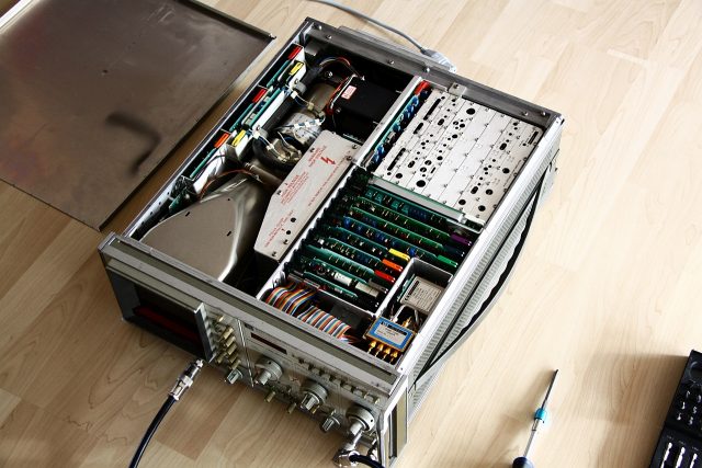
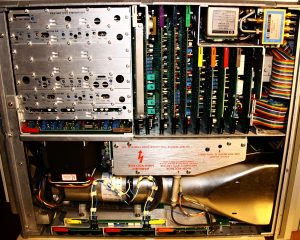
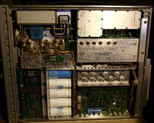
Tube and HV module boards on the left, control and display circuits in the right center, IF filtering and detection in the right back and the RF frontend with the YIG oscillator and 1st mixer visible in the right front edge. Most of the RF stuff is hidden in the right front bottom compartment with the 2nd and 3rd LOs filling the bottom right back.
Prior to the first turn-on, I inspected the device more carefully. Took off the top and bottom covers and looked for mainly mechanical damage.
The first and most obvious problem was the fact that the CRT tube was sitting loosely inside its shell, rattling around on movement of the case. Yikes! Usually, the tube should be fixed in some kind of a shock mount which allows it to move a little but not to strike any hard surfaces, preventing mechanical impact. The 8565A tube was mounted like that before, but the foam inside the front part of the protective shield had failed due to age, and it seemed like just enough had remained to protect the tube this one last time. It survived without any apparent damage! Pretty mad if you think about a thin, heavy piece of highly evacuated glass sitting in a super-clunky metal box, being hurled around in a truck. Phew!
While poking around inside the case, I next found a small metallic finger-like part:

This is obviously a contact wiper out of some kind of rotary switch assembly – could possibly explain the broken sweep time selector, since that is indeed a rotary switch. Unfortunately, the selector usually contains TWO of these, and for the switch to be dead both need to be gone. Wait a second…I know that it can only have left the case if someone opened the lid because the openings are too small, and that means if one was inside, the second one probably also still is. The big question is: Where? From my experience, in such cases the answer usually goes like “wedged in between the live and neutral mains” or “sticking in the HV supply”, or anywhere along those lines. Never expect loose parts to stay harmless, ever – and if you decide to anyway, try to stay away from flying fragments ;-)
In the end I couldn’t find the damned thing during inspection, which is partly due to the whole case being packed full to the brim with RF components, or maybe it really did get out somehow. Since the most crucial and harmful places were clear, I risked turning the analyzer on in the end, and it proved safe.
On the first look, everything seemed to be in order. The tube came on, all readouts worked – except for the center frequency. The oscillator certainly did sweep a frequency range around DC according to the screen output, so the voltage controlled YIG oscillator had likely survived. Still, the center indicator showed a steady 0.000 GHz. Judging from the manual, this should be an error in the driving circuit. The indicator is an actual voltmeter that shows the selector voltage, which means that there is no way a missing oscillator output will force the display to zero. The first LO is then driven by a circuit that translates this voltage into the necessary tuning currents. This translation is necessary because the LO is usually not identical with the received RF frequency for filtering reasons. On a hunch I opened the top lid again and pulled all the modular boards again after cutting power. The connectors were clean and shiny, but something seems to have been loosened during transport, because after replugging of all cards and reachable plugs the center selector worked just fine across all bands.
So much for the past, let’s check what works right now and what doesn’t:
The sweep time selector is obviously dead, probably for mechanical reasons. Fortunately, HP designed the device in such a way that if all contact wipers in the switch are lost, the timing circuit will switch to AUTO mode as failsafe. Could be worse. AUTO means that the device selects the ideal sweep timing from a table, which is usually ok. In some cases it becomes a nuisance, but this fix has a somewhat lower priority.
Another part that seemed to have become stuck is the RF attenuator. If -10dB is selected, no relay clicks on inside and the real attenuation is actually 0 dB, which can become dangerous for the first mixer. Also, all odd attenuation levels that employ the the -10dB-segment are also wrong. This may be due to a contact problem because the attenuator selector is built the same way as the sweep time selector, and needs to be fixed first.
In conjunction with the attenuator, something is wrong with the REF LEVEL readout. This is given on the dial itself by a very clever mechanism, and also on the screen bezel via LED modules. The two values differ by 10dB and the dial shows wrong values if the highest attenuation and lowest ref level is selected, so this is just a misalignment of the dial.
The REF LEVEL setting also shows weird behaviour. Each step of the dial should increase or decrease the trace amplification by a fixed 10 dB. For the first +50, amplifiers are inserted in the IF section while for +60 and above an offset is applied to the logarithmic amplifier. This is handled internally according to noise figures. The gain stages are composed of one +10 dB and two +20 dB circuits where the second +20 is enabled only for gains of +40 and above.

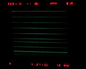
0 dB absolute amplification is just under the bottom end of the graticule. Visible steps are (from the bottom) +10, +20, +30, +40, …, +90 dB.
Have a look at Fig. 5. To take this picture, I enabled persistence display, noise averaging and applied no input signal, which results in a horizontal line. I then stepped through the REF LEVEL settings in WRITE mode and switched over to STORE mode. The 0 dB gain line is just below the visible screen area, and you can clearly see the wrong distance between the +30 and +40 dB lines. This happens only for this one specific step, which hints at a misalignment of the second +20 dB step gain amp.
Finally, one of the two 50 Ohms termination plugs for the mixer and 1st LO BNC connectors was missing. Can be bought, no big deal.
With these exceptions, the condition of the device is pretty good for its age. It probably needs a complete recalibration soon, which depends on when I can get access to the necessary precision references, and how I get them close to this mother of a beast. For now I will concentrate on making it fully useable.
An extra that I want to try and add in the future is a 10 MHz reference input. The 8565A has an analog PLL that can lock the first LO to an internal 1 MHz crystal reference to stabilize it for precision measurements. This crystal takes a long time (~30 minutes) after turn-on, so the lock will drift some for the first ~30 minutes. Since I own a Trimble Resolution T frequency standard module, I want to be able to at least lock the 1 MHz oscillator to the external 10 MHz reference as it is standard for most modern units. At this point, a modern digitally controlled PLL really would come in handy, but that brings its own problems. The whole issue with the 8565A is even a little more complicated than I can explain right now because of the technique used to achieve the locking, but it should be possible. Mostly without extensive modifications to all original circuits I hope, since I really don’t like to mess around with such a beautifully clean design. Fortunately, two of the internal HF mounting spaces near the back of the case seem to be unoccupied, so I could design my own plug-in module. Or I manage to get my hands on the 300/100 Hz IF filter option modules that are supposed to plug in there.


Professional HP instruments of that time were really good RF performers before digital “revolution”. I use one 8565 since a lot of years. full doc may be obtained easily at G1SLE. Input attenuator mechanism requires care for fixing. Same with attenuator cells or front end mixer (CT1DMK)
unfornunatly, my center F display also 000 since a couple of days. No improvement with check and cleaning connections. Have to look further as F scan is ok! is anybody using DG4RBF counter module (VHF Com 1/2005)?
some writing about at http://www.f6evt.fr
thks for nice blog 73 f6tem
Hi with a deeper check of various connectors, F center display is now fixed.
yr approach was fully right Tks 73 f6tem
Hallo, habe einen defekten HP 8569a geschenkt bekommen, der ist wieder soweit fertig – hat noch 2 Macken.
1.) Abschwächer -30 dB schaltet nicht immer – denk da gibt es keine vernünftige Lösung für ? Oder ?
2.) die Led Anzeige zeigt -10.000 und ändert sich nicht
Hat da jemand noch Ideen zu ?
Grüsse df6yl
Hi Pitti,
dein Problem mit dem Abschwächer kann ich gut nachvollziehen, macht meiner auch. Allerdings nicht nur die 30dB-Stufe, sondern die 10, 30, 50. Ich vermute daher mal, dass es in meinem Fall die 10dB-Einheit ist. Anfangs hatte ich da Probleme weil eine der Mechaniken komplett hängen geblieben ist, aber das ist es nicht. Ich bin noch nicht zum Suchen gekommen, habe aber eher das Gefühl, dass der Drehschalter schuld ist. Besonders, weil der Abschwächer gaaaanz kurz anzieht und sich dann wieder ausklinkt. Hast du mal die Kontaktfedern am Panel vorne geprüft? Ansonsten könnte es auch Dreck in der Mechanik sein, weil neben dem E-Magneten da auch ein Schaltkontakt für die Steuerspannung drinsteckt, um die Spule nicht ewig zu belasten. Eine Art bistabiles Relais also. Da kommt man aber ran, ohne den HF-Part aufzumachen.
Wegen der Anzeige schaue ich am Wochenende mal in die Schaltpläne, vielleicht fällt mir das was ein. Ist am Ende ja nur ein spezialisiertes Voltmeter, das die Steuerspannung der Yig-Baugruppe skaliert und anzeigt, das muss sich finden lassen :-)
Beste Grüße, dl6mu
Hallo Mario,
danke fr die hilfreiche Erörterung, 158 V etc. betreffend. Unabhängig davon spielt der Brocken: baseline clipper, intensity und an der Z-axis herumgemessen und wie Phoenix aus der Asche habe ich ein Bild. Der Sache mit 158 V muß ich aber nachgehen.
Bitte gebe mir Deine E-Mail an. Telefonisch ging über die Auskunft nichts (habe über DARC Deine Anschrift).
Thanks again and take care.
vy 73 Gero
Hallo Mario,
möchte mich für die Antwort, den 8565a betreffend, bedanken. Hatte die Hoffnung, früher an den (die) Fehler zu kommen. Bisweilen steigt auch die +158 Volt bei Umschalten von WRITE aauf STORE oder CONV aus, aber nur ab und zu. Muß Gerät wieder aus- und einschalten.
AN # 3 der A4 Z-axis kriege ich kein Oszillograph-Signal, nur eine Spannung von + 9,3 V ist messbar, bei sweep source ext oder man sind es 0 V.
Die deflection voltages zu entfernen brachte kurz einen dot auf dem CRT, der aber gleich verschwand. Pulling out X- oder Y (A6, A8) traute ich mich nicht.
Habe den Eindruck, dass A7 faul ist.
Ich melde mich wieder.
vy 73 de dl2iz, Gero
Hallo Gero,
lass dir Zeit. Ich muss meinen Analyzer die Tage aufmachen um endlich den Log-Amp fertig zu prüfen, dann werde ich ein paar Vergleichsmessungen machen.
Die Sache mit den 158V solltest du eventuell zuerst kontrollieren, falls das von allein passiert. Laut Manual hat die Quelle eine Crowbar am Ausgang die bei Überspannung (VR9, VR10, U > 168 V) den Thyristor Q30 durchzündet. Wenn du sagst, du musst abschalten um wieder Strahl zu bekommen, würde ich dorthin tippen. Vermutlich geht die Kontroll-LED Ds5 mit aus. Da die Spannung von der 15V-Referenz abgeleitet wird, sollte die eng toleriert sein – muss also einen Grund haben, wenn die abhaut.
Wenn also die 158V ausfällt miss mal auf A40 die Ausgangsspannung an 158V (sollte absolut null sein), Spannung über R47 (deutlich größer 0) und die Basisspannung von Q9 gegen Masse (auch größer 0). In dem Fall wäre die Regelschaltung davor schonmal zu prüfen.
Ich denke zwischenzeitlich über deine Messwerte nach.
vy 73
HI,
I have an HP8565A and these last few months the frequency shows as 0.0000 on both the CRT or the LED display.
All voltages are within tolerance values and the 10V reference Voltage is also fine.
Any ideas?
Thank you in advance
Mans
I’d say the most probable cause is a bad connection.
Have you tried pulling the color-coded plugged PCBs in the right-hand compartment and reseating them? (Except for the covered HF-boards in the back, no need to pull those…)
Also try to check or re-seat the connectors behind the right front panel, those are not all locked in place and might become loose if there is some force on the cables.
Hallo Mario,
since years there is a 8565a in the corner to be refurbished. But some problems have to be solved: in the CONV condition there is a black screen and in WRITE the screen is green but no other reactions. Long time before I could make measurements in CONV conditions, after 15 to 20 minutes the CRT became dark. My suggestion is that their could be a defect condensor in the store assembly A7. I also check Y-Driver, X is supposed to be o.k.
May be you have good ideas to help.
Thanks for replying.
Gero DL 2 IZ
Hi Gero,
hmm, somehow sounds to me like either the blanking is active or the intensity control is bad, which is partly the same. I’d say either A7 or A4 (Z-axis). If I am not mistaken, you could test X and Y by pulling A8 and A5 out, should not lock the unit and just remove the deflection voltages to center the beam.
Can you check the PEN LIFT output on the rear panel? Testing point #3 on A4 would also be interesting, that’s the intensity setpoint voltage. Although this can be up to 158V, tricky measurement if you don’t have the extender board to raise the plug-in boards out of the analyzer case (I don’t).
Also, does the green-screen brightness vary in WRITE mode if you change intensity? It should become brighter if you turn counter-clockwise.
Mario, DL6MU (der hier übrigens nichts gegen deutschsprachige Kommentare hat, falls Dir das lieber sein sollte :-)
Hi…
On your oppinion: how this unit performs in terms of age of components? Is this maded in true fasion of old HP meassurement units? I also want to acquire similar device for microvawe experimental work. Please add on your blog some aditional pictures of unit interior.
Dubravko
Yes, it is definitely built in the old spirit of lab equipment! Maybe not special for the market it was built for, but very much so for ham radio purposes. Everything in the RF frontend block is heavy metal encased, rigid coax, top class connectors, thick silver and gold coatings. Up to the 2nd mixer the circuit is built of discrete RF modules, each in its separate milled metal case. The parts beyond are also cased, but in rather large module packs.
I am not yet through with the whole testing and calibration process for lack of certain instruments, but what results I have right now indicate that the unit is mostly within its original spec, which is amazing for an uncalibrated device. From inspection it seems like some capacitors might go bad in a few years, but that is not certain. Some plastic parts that might crack. The switches on the front panel can become a little brittle, which is mostly cosmetic. For wear of electrical components, I only have found one suspect PIN diode in the logarithmic amp that might have gone bad, but I am not yet sure of that. Also, this is the relatively low frequency section, so there should be lots of suitable replacements.
Up till now I have successfully used it for some measurements on directional couplers (<1 GHz), a wideband noise generator (1.5-2.5 GHz) and some modified sat equipment (9-12 GHz). It was very easy and fun to work with. The results were as expected, no surprises. Zero reaction time to setting changes, but it takes a while to warm up its circuits after turn-on. You can measure after about 10 seconds CRT warm-up time if you don't care for precision, of course. There usually is a tiny bit of amplitude and frequency error in the cold state which fades away over the first ~30 minutes or so.
I forgot to take pictures when I took off the bottom cover to the RF compartment (noticed that while writing), but I'll catch up on that later tonight, no problem. Shout if you have any detailed questions, and I'll see if I can answer them ;-)
Cheers, µ