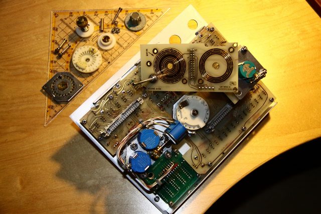
As I already mentioned, the highest priority fix is the input RF attenuator. To get access to this, the control panel must be taken out since the connector is placed at a slightly inconvenient place – the bottom of the motherboard. Unfortunately, right beneath this is the aluminum carrier plate that contains all the RF circuits consisting of semi-rigid coax and clunky metal-jacketed modules. I first unmounted the top, bottom and right side panels, which was an easy job:
- Loosen the single screws at the back of top and bottom covers and pull them off towards the back.
- Remove the two screws holding the carrying handle and pull off the side panel along with it.
- Also remove the top and bottom plastic inlays from the front aluminum frame, these cover up the panel screws.
- Remove all visible screws from the top of the frame that seem to belong to the right panel (should be 3) and also from the bottom (should be 2). Take care not to remove the 2 rightmost screws on the bottom, these hold the front connectors and are best left in.
Now pull the control panel right out.

If it sticks, the points to watch out for are the N-type RF connector and the PCB edge of the sweep time selector. Gentle pulling while wiggling the panel up and down some will bring it out. Remove all connectors from the backside. Don’t worry, the plugs can’t be interchanged. Set the panel on a flat surface, front side down (Fig. 1).At this point I first checked the selector switch, but everything was okay. All contact wipers are present and switching works just the way it is stated in the manual. So the problem must be related to the attenuator itself. Because the attenuator is fixed in a tight spot and held by the rigid coax lines, I used the chance and fixed the sweep time selector first. Let’s take it apart.

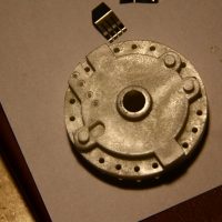
Lots of small parts. In the end only three screws needed to be removed to make it all come apart, but take care that none of the spring-loaded balls get away (see Fig. 2). The gears are probably sticking on the axles because of some glue-like grease residues, so be careful when applying leverage. After removing the switch rotor, the damage becomes obvious (Fig. 3).

I considered different methods for replacing the wiper, but in the end I made a new one (Fig. 4). The material is some kind of coated steel sheeting and very similar to the kind used for shielding boxes in mobile phones. I had some leftovers from a broken tablet that I disassembled some months ago that had just the right strength. It can be cut with scissors after copying the design with a felt-tipped pen. The holes were just punched through with a needle, the edges of the holes bent outward and hammered flat. I then drilled the broken-off plastic pins out with a small 0.8mm Bungard PCB carbide drill bit that I normally use for PCBs. These are so sharp that the hole can be finished with ease by just twirling the bitbetween two fingers.

Some small screws taken from an old notebook hold the wiper in place now. The original wiper is fixed in the same way. Before replacing the rotor, I ran the wiper blades over a soft eraser-like abrasive block several times to remove any sharp burrs that might damage the gold plating. Also, check the alignment to the surface and tweak the blades with pincers if necessary.