Thin film electro-luminescent (TFEL) displays represent an interesting, if somewhat anachronistic display technology, now that we have high-contrast LCDs, plasma displays and of course OLEDs. The latter are actually closest to the principle of TFELs, and their primary optical advantage is identical: light-emitting pixels instead of backlighting, for maximum contrast. Where OLEDs use an organic polymer, which can be excited to emit visible light by applying an electric field, a TFEL does the same with an anorganic dielectric material like e.g., gallium arsenide (GaAs). The emitter pixels are sandwiched between two layers of transparent dielectric to insulate them from the transparent electrode grids on the front and back glass cover of the display panel. When a high-frequency current is applied, a current flows through the selected pixel and the emitter material lights up in a beautiful, saturated orange – in my opinion the most interesting aspect about this technology. Remember the old terminals with the amber CRT screen? Close! In contrast to OLEDs, EL displays are also able to tolerate much harsher environmental and mechanical conditions, which makes them ideal for applications in heavy machinery – or living room gadgets, when they are retired.
One flaw, which later also afflicted EL’s relatives plasma, VFD and OLED, is the infamous burn-in. After long periods of displaying the same picture, the insulator and emitter can degrade, causing increased leakage current (pixels active when should be off) and brightness reduction (pixels dim when should be on). Both usually occur at the same time for worn pixels. Fig. 2a/b show how this looks. Off-screen ghosting strongly depends on the display drive and on the picture displayed. Both pictures were taken in test mode, which severely over-exaggerates the burn-in.
In spite of all that, many such modules are available in good shape today. Although prices on ebay are sky-rocketing to say the least (500-1.200 EUR per piece!), you can get lucky to find some original Finlux/Planar at low prices. I have managed to acquire two over the years, one being the EL640.400-CB1-FRA featured in this post. This one is my experimenting module since it already has some burn-in from excessive prior use. The other is brand new and will go into a retro-style terminal display, together with a Raspberry Pi as a networking backend and a motion detector to reduce power consumption.
Unfortunately, controlling these displays can be quite a pain. At least, complete datasheets are available everywhere, so we don’t have to poke in the dark. The default source signal is VGA compatible, although it is not analog but digital. For each pixel, a single bit (on/off) is sent, along with the corresponding video clock, hsync and vsync. Unless the feeding device has a matching VGA feature port (more common when ISA VGA cards were still “hot”), fast I/O is required to get a stable image. Basically, the display with 640×400 pixels needs to be scanned once per frame, per second. For each line 640+4 video clocks are needed, including the horizontal sync. After the last line, a blank is sent before the vsync to terminate. This requires another whole line. In total, this amounts to e.g., 644*401*20 = 5.164.880, or 5.165 MHz pixel clock at 20 frames per second. So, all in all none of the easier tasks in comparison to a SPI/I2C display. Additionally, the display does not have a RAM which stores the received image for automatic refresh, but instead the video data is shown directly as a scanline. The perception of a static image comes from rapid scanning, as with CRT tubes.
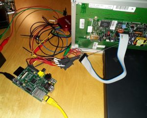
My first attempt at full-res VGA using an ATMega CPU does not bear inspection. Although I got an image, the signal was obviously much too slow. Much better results were obtained by porting the program to a TI ARM Cortex M3, which ran at 72 MHz and made a clean and stable checkerboard picture. It did not do much else, though. So for the next attempt, I am trying to get the signals from a spare Raspberry Pi gen. 1 GPIO port (Fig. 3a). Mind that this is all quick & dirty, purely for the sake of experimenting what can and what can’t be done, and learning more about the Pi GPIO. There are many more efficient methods.
So, how do we generate the signals? I am currently using a C++ library for fast GPIO access found on hertaville.com. According to the author of the post, toggle rates up to 25 MHz should be possible on the Pi 1, although I doubt that the GPIO layout is really capable of such a speed without a suitable buffering circuit. If true, this should suffice for a 5 MHz clock. I can additionally lower the required clock frequency by sending two consecutive pixels in parallel as the display supports one additional data line. The connection to the display is set up as in Fig. 3, all remaining signals are left unconnected. Depending on the precise revision, an additional supply voltage is needed for the integrated DC-DC high voltage converter (e.g., 12V for the -CB1-FRA here). Finally, the display has to be configured for test-mode OFF, dual line data ON using the jumpers on the backside. Terminal layouts and function polarities differ between versions; for the -CB1 a single jumper in position 3 is required.
The actual VGA generator is a simple continuous loop which cycles through the individual steps. After some trial and error, I found that additional delays to create the correct timings make things worse than simply letting the program run as fast as it can. The display can read much faster than the I/O can write anyways, as long as the waveform is still in decent shape. There also seems to be no overly sensitive clock regeneration or PLL inside the TFEL controller. Still, regular clock intervals are to be preferred. My program flow is as follows:
[text-box]
- Init port and load 640 x 400 x 24bpp BMP file (or any other image source).
- Start writing first buffer line by applying pixel values to VID0/1 and sending clock.
- At half line, pull VSYNC high for the 8 VCLKs. Then release.
- When line finished, pull down HSYNC (is high on idle) and add 4 blank VCLKs. Then relase. The display will only show the last 640 pixels before a HSYNC is given, so the four blanks will not appear.
- Start next line in same shape, but without the VSYNC part. Repeat.
- At end of frame, send one additional line of 640 blank VCLKs plus 4 with HSYNC low. This will force the display to write the last line before skipping back.
- Start from beginning.[/text-box]
Each step is handled by a single (inline) function which is called by its parent in a loop. Each loop cycle contains multiple calls to mitigate loop condition overhead. Now, this is not the optimal way in which to send a timing-critical signal, but the result justifies the means in this case as seen in Fig. 4b. Courtesy to Archlinux, my favorite distro which powers the attached Pi ;-)
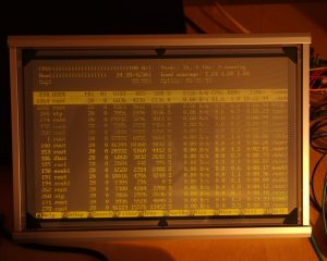
The image still looks ragged on the edges, which is at least partially a timing problem and can also be observed when displaying a grid or diagonal lines. I could nail down the timing issue to the line-writing function due to an image distortion appearing every 16-18 lines, relating to the number of writeLine() function calls. A parameter was originally passed to this function to indicate the current line to be written. A little piece of comfort, which seems to have created quite some compiled code. Instead, I now implemented a global pointer to the current pixel, which can be used by any function directly. Afterwards, the second issue was found easily: swapped data lines were causing the zig-zag edges. To top it off, I included a cyclic read of the /dev/fb0 framebuffer to mirror the active terminal on the EL display as seen in Fig. 5a/b. Aside from flickering and some residual distortions that are probably caused by the line levels and still need to be investigated, the output is pretty useable!
Looking good! Let’s have a look at the actual timings being generated.

You can see the parallel data transfer on VID0/1, the HSYNC at the end of each line and the rather sparse VSYNC. We actually achieve a frame rate of 29 Hz. But wait – where did that huge break at 8…14ms come from? The answer is simple: the task scheduler just decided that another program needed attention, and since I took no precautions it simply sliced time out of my running loop. I measured once more to get a good frame, finding an actual frame rate of 35.2 Hz, which is awesome! The HSYNC rate is 14.36 kHz, and the pixel clock is running at 4.545 MHz. Unfortunately, the clocks are not really stable, which is both due to the scheduler and the program flow, which could use some additional optimization. Also, for fear of scaring off the ghosts of good fortune, I have not yet hooked up my scope – my current working hypothesis is “if the Logic can read it, the display can, too – and to hell with the edge slopes!” ;-)
My list for further speed improvements includes:
- Switching to pointers everywhere instead of the array addressing I use currently, allows for more efficient loops.
- Combining the write access commands for individual pins which could be switched at the same time, as the library currently only allows for single-bit access.
- Use a timed interrupt to get a stable framerate and release the CPU in breaks, to try and prevent interruption by the scheduler at unfortunate timings.
- Include a line buffer to normalize levels and lower source impedance for better signal edges.
- Move to a multicore Pi.
- Ditch the whole concept and use the integrated DSI of the Pi for digital VGA. Or use some kind of external IC which can be fed through SPI…but it is nice to see how fast I/O manipulation can be on this cheap board.
You can get my current (experimental) source here: el_640_400.zip
The program accepts three commandline parameters which are –framebuffer (tries to grab /dev/fb0), –bitmap (reads 8-bit RGB logo.bmp from the program dir) and –pattern (test pattern generated by initFB). The flow is not yet optimized for timing, there is a lot to be done ;-)
Before compiling, pull the mmapGpio-library from the link given above and copy the files mmapGpio.c and mmapGpio.h into the source directory. Then just run make. The pin mapping for the Pi can be changed in main.cpp.


Please I want cooperate in video project to display machine data from vga to LE640.400
Or convert the input data to standerd vga
Hi Mohamed,
see https://electronics.stackexchange.com/questions/228825/programming-pattern-to-generate-vga-signal-with-micro-controller (or rather, https://i.stack.imgur.com/WKxmm.jpg). The signal is already actual VGA, in the best case you just need to connect properly. The data bit of the EL display can be connected to red/green/blue or all three together – if only one bit is used. In the case of two bits you would need an electronic switch, which alternates the two signals with each cycle of the pixel clock. For VGA, you do not need the pixel clock, just the two HSYNC/VSYNC and color signals. Then it is a question on whether the receiving display can work with the timings required for the EL display. Adjusting this needs advanced hardware for signal processing and conversion.
Refer to The vedio signal from the machine to EL640.400-CB1
Can be displayed in vga monetor
If it yes please advice
would be great to get the source, have multiple Display laying around :)
Very true, have been distracted by the job :-/ File is up now, have fun!
It could use some more timing optimization though, I did not yet get around to that.