This article is about one of my recent spontaneous projects. A few days ago, I got lucky on an ebay auction and picked up a broken Acer K330 projector. I often look for these kinds of offers because I have spent several years in the audio/video repair business and am pretty confident in my skills when it comes to fault-finding. So I figured, saving some money by restoring a broken device couldn’t hurt.
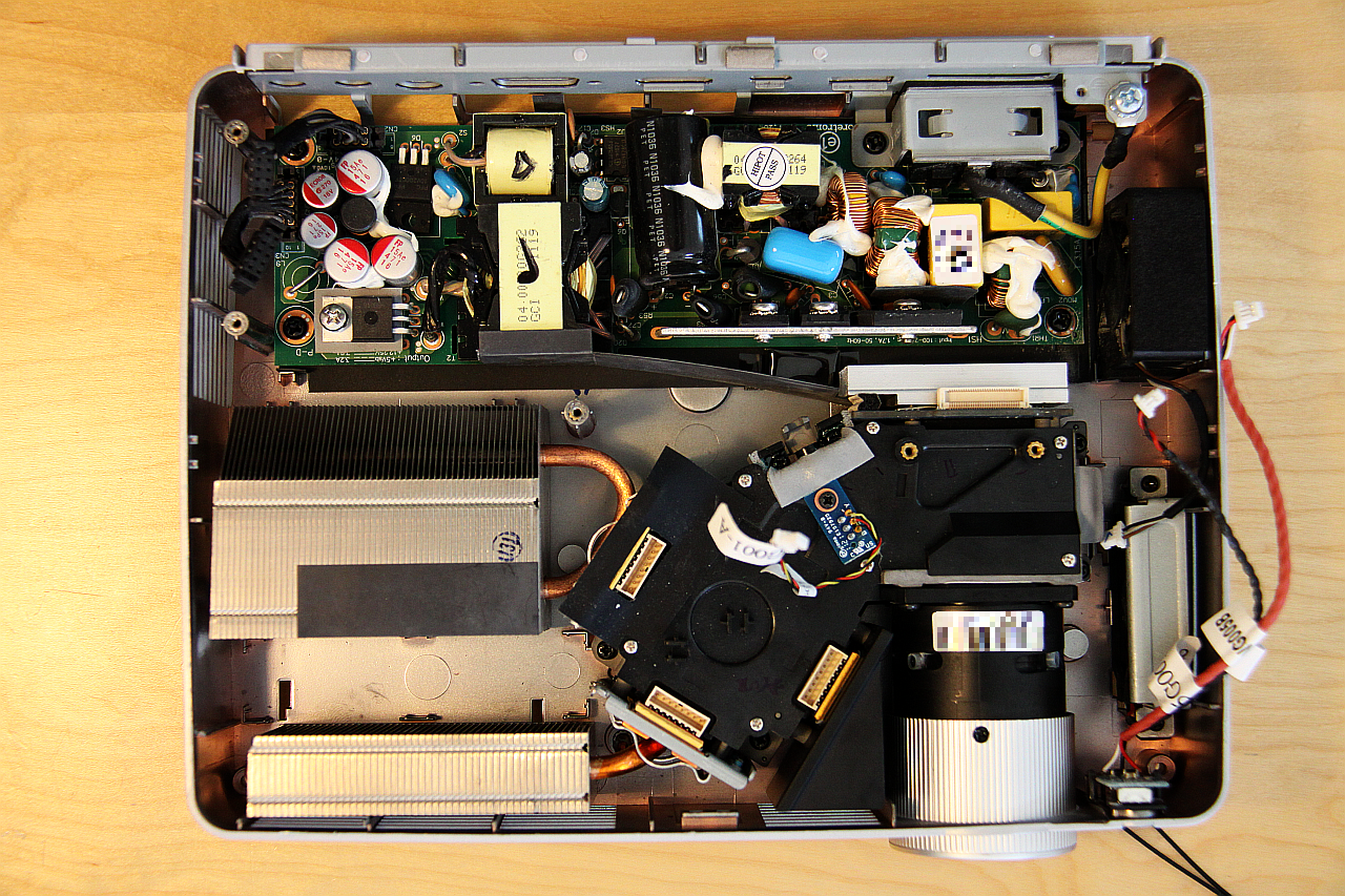
Fig. 1: Acer K330 power supply and optical path.
First some facts and features: The K330 uses a three color LED module, which promises a long lifetime and low energy consumption. A Texas Instruments DLP module handles image generation. In sum this lets me hope for good contrast and strong colors, even if the brightness of 500 lumens doesn’t seem that much. An interesting thing about this DLP chip is that it uses an uncommon diamond pixel grid for size reasons. Diamond in this context means that the pixels do not form a rectangular pattern like in the usual TFT monitors but rather a grid of 45° rotated and slightly squeezed, not completely rectangular tiles. Of course, this means that internal resampling has to occur to map the image from the rectangular domain onto the diagonal domain of the IC.
So, this projector was obviously broken when it arrived – what a surprise. The seller had already informed me that it had suffered from overvoltage of unknown cause. The VGA picture was supposed to be very green-ish, the HDMI input dead in whole and the media player erratic. A slight flickering in the picture was also mentioned. I’ll take you through the repair process for this device from here on. Continue reading →
Anyone who has already tried to use some kind of tablet device for writing should know that there are fundamental differences between screen types.
The most common is the capacitive type, where you use a finger or some kind of conductive pen to write on a glass surface, while the touchscreen device captures movement of the capacitance change through a grid of transparent electrodes on the backside of the glass. This works, but it sucks for writing precise text or drawing sketches. You can find these screens in almost every modern smart phone, tablet PC or kitchen appliance. They are cheap!
Next is the resistive touchscreen, where a small, hard point presses down on a plastic surface. The touch element is composed of two pieces of clear foil, coated with a conductive material. While the two layers stay isolated when there is no pressure applied, the pen forces them together in a certain point, forming a conductive path. By knowing the specific resistance of the surface coating, the circuit can determine the position of the pen tip by measuring path resistance from different edges of the screen. This type was pretty popular in PDAs (which have by now been fully replaced by smart phones, what a shame ;-) ) as well as the almost equivalent navigation assistants – and is not that common anymore. Writing performance is fair but not exceptional, though.
The third kind is the most interesting one. Real tablet PCs (the ones with the flip-over display) have this normal-looking pen with the nylon tip, which you can use to accurately write on the glass/plastic display surface. Many even feature some buttons on the pen, some kind of eraser on the backside – and they are damned accurate! They have another thing in common: Most of them use technology by a company called Wacom, also producer of digital writing and drawing pads for artists.
This type is called a “digitizer screen”, and it uses a sensing panel *behind* the actual display to recognize and track the pen. The digitizer panel contains an amazing set of surface coils to provide an alternating magnetic field through the screen. Inside the pen, there is a resonant circuit which uses the field energy to transmit the button states and even pressure on the pen tip back to the coil. By monitoring the strength of the resonance through different surface coils, the digitizer then calculates the position of the pen above the surface. In other words, you get a high-res info about the pen position (easily above 25.000 points resolution along the surface edge, depending on the digitizer type!), you know the pressure applied, button presses on the pen and even where the pen is when it is not yet touching the surface.
I recently disassembled a trashed tablet PC (Toshiba Portege) with a broken motherboard for interesting parts, and came across this:
Fig. 1: Backside of Toshiba Portege LCD module. Wacom digitizer (red/orange foil) and control logic (PCB in top left corner) are visible. LCD control board on the bottom.
The LCD panel is a LTM12C328T type. Attached to the backside is a SU-010-X01 tablet pen digitizer, and the marking on the ICs clearly suggests that it is made by Wacom. This would make a fine graphics tablet – but how to attach it to any other PC? Continue reading →
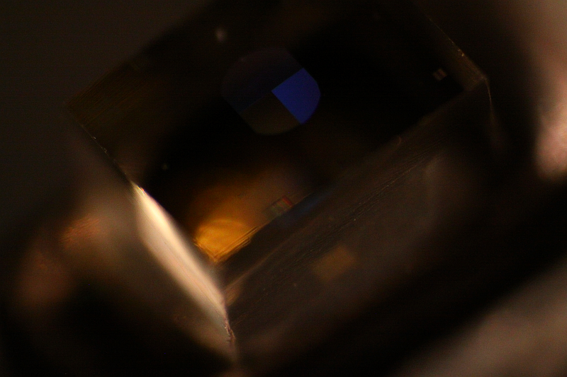
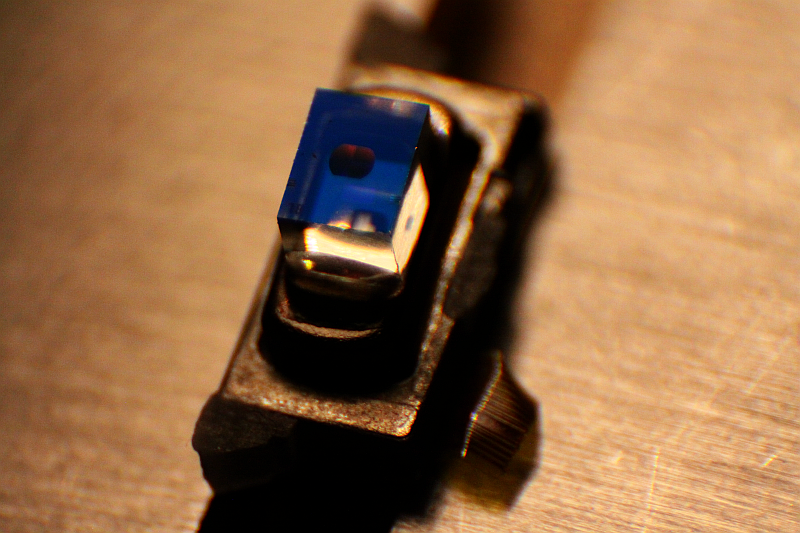
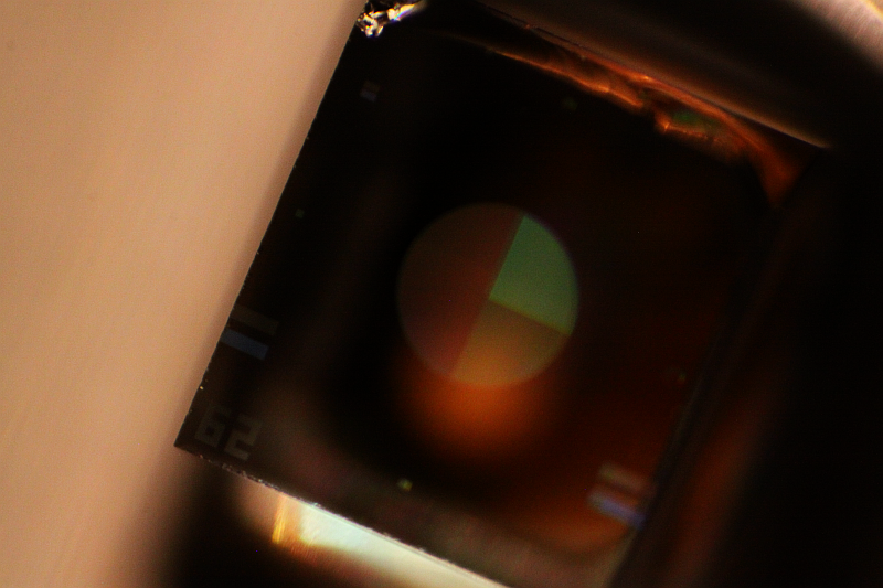
During disassembly of some old CD/DVD drives, I stumbled across a pair of *really* beautiful laser diodes. Not much use for them right now, except practicing macro shooting – pretty hard to get good pictures of the structures inside and the dichroitic filter blue at the same time.
A few days ago, a friend came over to talk about some microcontroller related projects. One of the topics was distance sensing, or rather proximity/movement sensing with low technical effort.
The basic idea was to detect movement of an object or person within a short distance to trigger events. Typical sensors for this kind of application would be passive infrared (PIR) modules, radiowave sensors (microwave or radar) or active infrared distance sensors. All of these can be quite pricey, perhaps with the exception of the PIR, which cannot detect objects very well.
So, I thought about how the goal could be accomplished with standard parts. Active infrared is the most simple choice. Continue reading →
So…it’s been a while. Somehow I thought, I’d have finished the CNC writeup by now, as well as my plans for continuing work on my plasma-bar meter project. Things turned out different.
I got into my Bachelor’s thesis after completing the preceding seminars, which kept me busy since june ’13. The topic is centered around signal power based speech DOA estimation using directional microphones, very interesting stuff from the domain of signals processing. I had a very interesting time learning lots of new things, and somehow I also wanted to get hands-on with the matter since attending several advanced DSP courses during the last two terms.
While working on the thesis, I realized that microphone array systems are really nice things to have to play around with. I decided to make my own, which I did in my free time in parallel to the thesis. Let me at least show some pictures as long as I still don’t get around to working on other stuff.
Whole array assembly.
Carrier construction for up to 8 microphones, spacing 25mm.
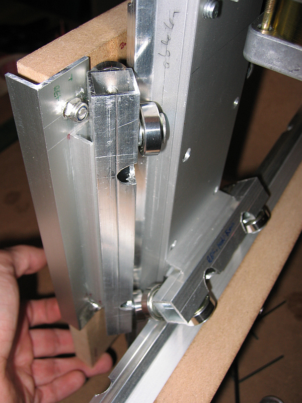
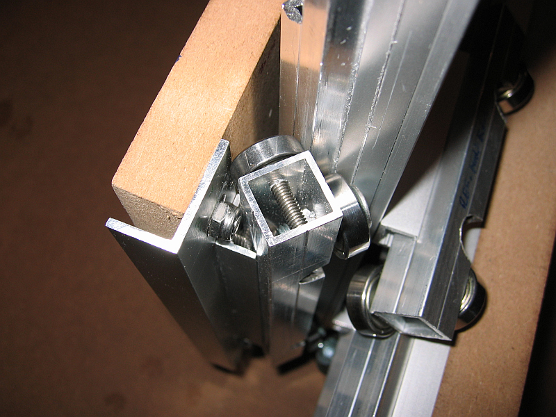
The CNC mill got into a working state right before christmas eve. I know it’s not a present in that sense, but still! :3
Some parts of it are still fixed with a lot of glue and tape (or zip-ties ^^), but for now that’s perfectly sufficient. Right now. it can already mill hard wood and MDF, so I will be redoing some critical parts that lack in precision and/or quality before I write up the whole project as one. Unfortunately, I fear that the original plan about using an (older) EPIA 800 board as a controller can not be followed, EMC2 just refuses to start on that thing. Grrrr…
More pictures and text will follow in a few day’s time. Until then, enjoy the holidays and have a nice and safe start into the new year!
Oh, right, and two Stellaris Launchpad eval-kits from TI that I ordered back in September arrived JUST ON the 24th. How great of a timing is that? I don’t care about the wait, it was well worth it and I knew up front – but thanks again to the girls and guys of the TI support, for solving all the technical difficulties along the way :-)
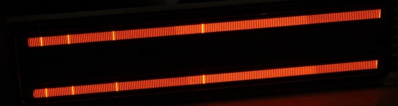
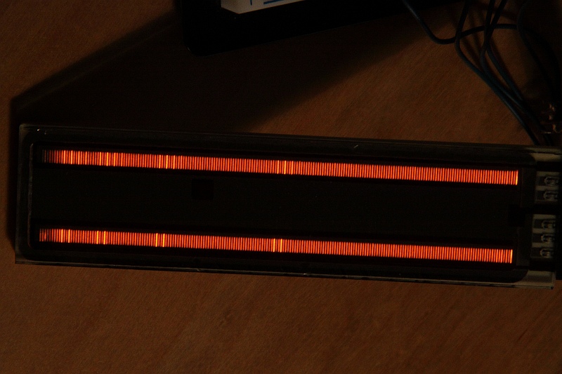
I picked up some unusual plasma displays from ebay some weeks ago, which I have been searching for quite some time now. The picture above shows an illuminated Burroughs PBG-12201 plasma bargraph display. They are pretty hard to get by now, and if available, prices are a real shocker. Some shops in the US that carry them ask for 230 USD and some even more. Sometimes they appear on ebay for about 50 USD, but you have to be real quick to get some. Best chances are with surplus stores that sell off leftover production stocks or disassembled devices that originally contained such tubes. A few very retro and very popular mixing consoles for audio applications used them as main VU meters (eg. made by Lexicon), as well as some current professional grade standalone meters (eg. RTW, one of those is where I first saw such a display and was absolutely fascinated by the deep orange hue). As they eventually get old and start flickering or burning in if not properly cared for, spare parts have become rare, and since Vishay – the most recent producer of these displays – has discontinued the product line in early 2012, I would expect the market to dry up even more.
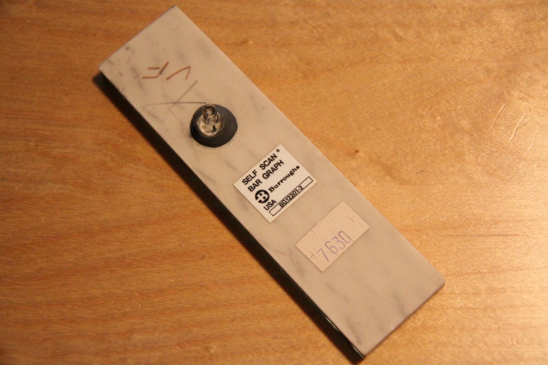
Back side with evacuation port
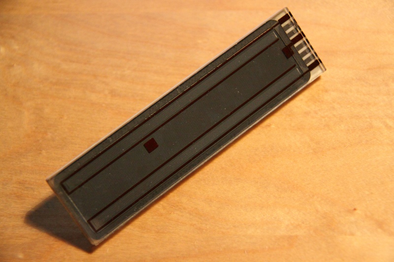
Burroughs PBG-12201
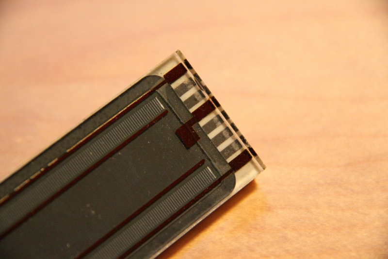
Closeup of contact strip
PBG12201 display with drive circuit
Tearing effect caused by the scan rate
Bar display with unsmoothed supply
Bar display with reservoir cap in HV circuit
Mine were obviously scavenged from some kind of device by a Hungarian ebay seller, he offered some 10+ pieces of the PBG-12201 type display for 8 Euros each – a real steal! I just couldn’t resist and got myself three of them, together with matching sockets. Thinking back, I don’t get why I ordered three instead of four…oh well, it’s done. The tubes show some signs of wear, like glass chipped off around the edges and burn marks on the cathode traces, but they all work fine. Continue reading →
Work on the CNC continues…the end draws nearer. I am currently disassembling the whole thing as far as necessary to clean up all the edges and burrs and fix the positions of the parts relative to each other using hammered-in stainless steel pins. After that, it is just coupling the threaded rods to the moving parts and bring the stepper drivers alive.
I figured out today that my router had a hand in those weird random connection problems. What made me especially nervous was the almost systematic way that DNS and other random UDP packets vanished from the ‘net during browsing or testing with various tools. The requests were shown to be sent in both the Wireshark protocols and the router packet capture, but an answer never arrived. As it turns out, Enterprise-class devices have their firewall preconfigured to block UDP flood from inside the local network.
The definition of “flood” used here is:
“20 simultaneous, active UDP connections from a single computer on the LAN”
Now, somehow my setup managed to step over that line, and from what I gather on the ‘net I am not the only one experiencing this. Sometimes the system will run clean for a few days, then bug in increasing frequency until I get fed up with it and kill the whole DNS process plus cache. Apparently, this fixes the problem for some time as a good reset almost always does, but it is no permanent solution.
To debug, first turn on the attack-related logging functions in the router and clear the logs. Then call up “nslookup” on Windows based systems and fire some random URL DNS requests in fast sequence. In my case, after four requests the firewall kicks in and UDP flood warnings appear in the log. Maybe Windows 7 just leaves the ports open a little too long, I don’t know and I haven’t checked. However, since this feature has been turned off in the firewall settings I had no further DNS problems, and the speed of browsing has increased a little. Hopefully that was all there was to it.
Another point of interest: Some Netgear devices have developed a habit of kicking lots of NBSTAT-packets on the LAN, one about every 5 seconds or so. Seems to belong to some type of NETBIOS detection mechanism, though the sense escapes me. The packets are of unicast-type and therefore disrupt everything one could possibly have in the way of wake-on-unicast, which linux supports to wakeup devices from standby if they are talked to directly. NETBIOS features are nowhere to be found in the configuration menu, so I guess at some point the checkbox for that must have gotten mislabeled. The one responsible is “ARP broadcast” found with the LAN settings. Turning it off quiets things down a lot.
But: You lose the capability to show unknown devices in the LAN clients list for simple management of DHCP fixed leases. You can still turn on ARP for a few minutes if you need to detect anything, though.
I’ve been having some problems connecting to IRC through the miranda client on Win 7 lately.
Miranda features several “serverlists” for different IRC networks – QuakeNet in my case. Some of the lists work, some don’t, some work at some times. Now, upon clicking edit only one fixed web address shows up. The way this works is, the DNS server knows multiple IP subentries for those servers. You can check with some web-based lookup tools that show all of those entries. Windows’ own command (“nslookup <address>”) only shows the one delivered by the server, as it needs only one precise IP to communicate.
Multiple entries exist to balance load between servers, they are delivered round-robin. If you flush your dns cache locally (Win 7 wants you to do “ipconfig /flushdns” on the console in admin mode, for example) a new IP is acquired – and this one is ideally different from the one before. Now, because Windows does not clear the cache between requests for several logical reasons (it’s a cache, right?) the client program obviously also knows only one of the possible IPs. All the better if exactly that IP is down.
It took me quite some time to figure out where the problem was (all the while thinking there may be something wrong with the router or the net is just in a weird mood today). After checking the DNS entries sequentially using ping and a connection attempt through Miranda, I found to my surprise that while some lists work partially others are simply dead.
irc.quakenet.org
1/8 working
Compilation of all subranges
se.quakenet.org
1/3 working
de.quakenet.org
1/2 working
uk.quakenet.org
1/3 working
Remember that this data is momentary from the time I checked the servers. The status might be different now. Anyways, this is some russian roulette!
The lists may fluctuate though, I am pretty sure I got a connection using the german list at some time. It is also possible, that the lists are updated dynamically from time to time, but I haven’t seen it so far.
Fixing this mess is quite easy: just edit or add a list in Miranda for the corresponding network and enter the exact IP. You best find that one yourself by pinging, start with one of the shorter lists you are comfortable with. You will experience trouble if that server goes down, but at least then you will know what the heck is wrong right from the start. Saves time and nerves.