LED driver again

The first version of the LED switching driver just exhaled a portion of magic smoke. The IC is neither the culprit nor the victim, there must have been a short somewhere else. The sense resistor was fried and acted as a fuse, but it wasn’t fast enough to prevent the current blowing another transistor on the motherboard that switches power to the backlight. Funny, didn’t even know there was such a thing. Maybe that explains the weird current shortages at the LED driver input that caused some of the flickering. The LT chip seems to have survived just fine, again.

Whoops, forgot to mention: Yes, it has been running ever since the last post about the topic ;-) so far, so good.

Anyways, gotta do this one again. To counter the problems with flickering, the new driver will run from 5V of the HDD/USB supply, operating in pure boost mode. Stepping from 5V to 9.6V will never cause it to even get near the crossover point where it would need to switch from boost to buck mode, and there will never be a lack of control range.

To explain that part, remember that the LT3518 runs in fixed frequency mode and varies only the pulse/pause ratio of the switch that draws power through the inductor. Let’s also assume we are in buck (stepdown) mode and the output current (LED current) is the variable the IC is trying to regulate. As the output voltage of a step-down converter is proportional to the on-time of the switch, the switch needs to be open all the time when the input voltage drops to or below the needed output voltage (that is, the voltage required to drive the desired LED current). Now, the LT3518 has a limitation in its pulse-duration caused by the design of its internal circuits, which in this case results in a maximum on-time of about 92%. If the required on-time rises above that, the IC can no longer guarantee proper function and instead of opening the switch permanently the regulating circuit begins to glitch, which results in flickering, low LED current and whatever else. It is not a danger for the LEDs though, because whatever happens, a step-up converter can never reach a voltage higher than its input.

I admit that I was kind of slacking off to assume it would work alright somehow – well, it didn’t ;-) Lesson learned, that’s why I don’t mind this happening. Sometimes doing it wrong is the only guarantee you’ll do it right the next time. The next version of the driver circuit will come with full eagle layouts and stuff; so please don’t get too hooked to the old design. It is only usable if you can guarantee a, let’s say, 2V surplus over the typical output voltage at the input all the time.

The new design will probably be done and up here ’til Sunday this week, and there will be some extra stuff with the CNC (stepper driver ICs arrived, some work on the axis’)
Minor setback

Somehow I knew that this went over too easy. Fortunately, magic smoke SMELLS. Just got the battery out in time, but part of the damage already happened.

Defective LED
Bang!

Defective LED
...and another.

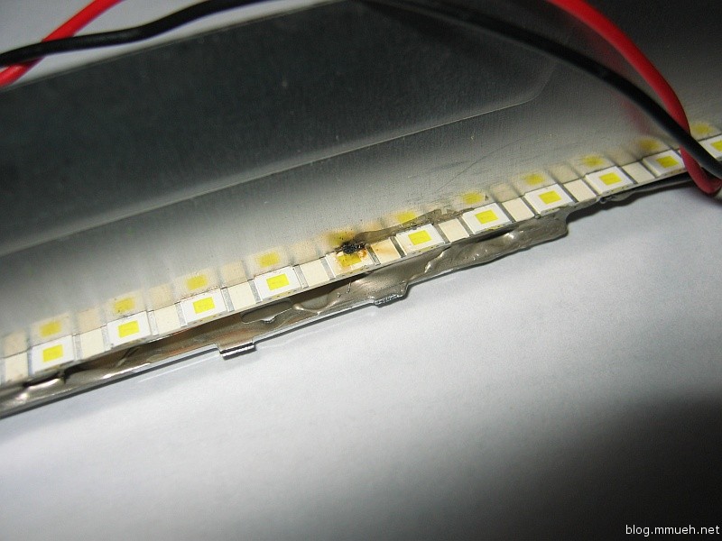
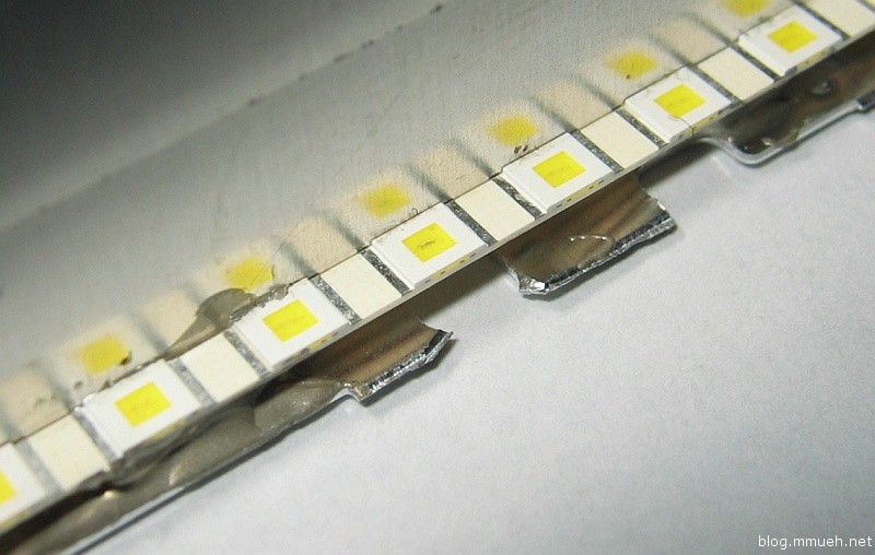
Some days ago, one of the triple-chains on the right half of the screen went out. While the darker area is clearly visible, the shadow is still illuminated by the neighboring LEDs. The cause is the LED in the second picture, the damage is only visible as a slight dark streak in the center of the yellow part. Then today the backlight fuse blew out of this world, and the reason is seen in the first picture. I knew this was a close call, but precisely “calibrating” the almost not existent isolation gap between LEDs and metal (by wedging a piece of paper in every here and there during glueing :-D ) gave me no no reason for concern. Maybe some flexing or thermal deformation did the rest.

Anyhow, got to rebuild this part. Not too bad though, the stripes are inexpensive and I wanted to include a diffusor sheet anyway. As good a chance as any I guess.

Edit: By the way, the driver circuit survived the whole mess just fine. That IC is some tough design! Haven’t managed to fry a single one of those so far.

DIY LED TFT Backlight

Today I finally got around to finishing my first design for a switching  LED display backlight driver. The circuit is built around a LT3518 switch mode driver IC working in buck (step down) mode in this application.

LED driver pcb topside

LED driver pcb bottom

Someone figure out why SMD hand-soldering always looks ugly on macro images…but trust me on this, the circuit works like a charm ;-) The flux residues don’t hurt performance, but you really do want to keep any solder-balls or whatever metalliccy is floating around your circuit away from the tight parts.  If necessary, rinsing it with alcohol while carefully assisting with a brush does the job, followed by a soft coating of plastic spray to prolong the circuit’s life.

My design was done rather quick and dirty because it needed to get done. Just don’t expect THE most absolutely high frequency capable layout, though I guess that prominent airwire in the first picture crashes this illusion anyways. Consider this more of a first prototype to check out what this chip has up its sleeve in buck mode after already trying boost mode on Tobi’s LED driver, which will also be documented later on. So far, it seems to keep up with my demands quite well, it will be modified and optimized later on.

Measurements (all taken at maximum brightness with a tRMS multimeter):

V in I in V out I out P in P out Efficiency
Mains 20 V 0.25 A 9.6 V 0.400 A 5.0 W 3.84 W 77 %
Battery 11 V 0.41 A 9.6 V 0.400 A 4.51 W 3.84 W 85 %

Higher efficiency on battery is just perfect, even though it is barely into the operating voltage range. The measurements made on the go, so the numbers might not be absolutely accurate. If there is time, the scope will clear that up. Also, keep in mind that battery voltage will drop some over time. According to standard Li-Ion specs, it ranges from 12.75 V charged to 9.3 V discharged (although I have never seen it go below 10.5 V so far).

The schematic and board layout will be available in the next few days in EAGLE format, together with more photos of the “implanted” driver. Need to clean up the parts naming and stuff first.

While I am on it, enjoy my wicked hand drawing skills :-D

Prelim. schematic
Prelim. schematic

Layout description
Layout description

A few things to add to the drawings: First, the schottky-diode is of SK34A type, secondly the ceramics are all of X7R-rating type (refer to datasheet of  the LT on this one) and thirdly the connection between TGEN and CTRL/VREF ist also an airwire, which can clearly be seen dominating the circuit in the pictures and is unbelievably oversized.

This article will be followed by some pictures of the LED array and driver mounted inside the display. The former was already installed before I started this blog so I didn’t think of taking some shots at the time. It is nothing spectacular really, some chip-on-board (COB) slimline LED modules bought over at led-tech.de, soldered together and cut to correct length, then glued into place instead of the CCFL with thermal conductive glue.

NOTE: While testing the device to its limits, I am experiencing some problems at very low system voltage. When on battery only, the notebook’s internal supply lines drop to around 10 to 12 volts as opposed to rock-solid 20V when the mains is connected.

This driver was designed with up to 20V and only down to about 12V input in mind, which means a maximum of 80% switching duty cycle at low voltage. I figured that the internal supply lines would be thoroughly regulated but was mistaken as it seems. As soon as the voltage drops a quantum too far while powered only by batteries (eg. more power is drawn by any device), duty cycle rises over some magic number around 96% at 250kHz (see data sheet) and flickering occurs as the IC loses control over the current. This is why there certainly will be a v2 of this, and it will be buck-boost-mode to handle low voltage situations even better. I might also want to fix minor problems with shutdown mode still allowing a very small current through the ICs internal switch, but in comparison this one is totally unimportant.

Right now the v1 driver is successfully implanted in the screen bezel and works nicely. Screen brightness even beats the original CCFL backlight, though the lower screen border is not absolutely uniformly lit. I could care less, thanks to the windows taskbar using up that space. The notebook is a SX65S by the way.