CNC – Step 1

Alright, so I finally decided what I want to do as kind of a long-term project in the coming time: A CNC mill which will get heavy use in the fabrication of PCBs, faceplates and enclosures. My case-building skills plain suck, so this nifty device will be helping me in the future. Also, this is my first real all-out mechanical build – meaning no straight way to the goal. In the end, it will probably have become a lot more expensive than I currently still hope for, but we’ll see about that ;-). (Account the extra expenses to learning and refilling the scrap parts box, distracts the wallet from groaning somewhere in a dark corner. Works most of the time.)

Sketchup of cnc mill

As I already wrote above, the main tasks for the machine will be PCB milling and drilling, machining wood, acrylic, plastics and aluminum. Maybe copper, and in the far future I want to take a shot at some steel sheeting, but all that is off the radar right now. I will try to aim for high precision and adequate stability. A portal mill seemed like a good idea at the time, especially because a moving table makes the machine just so much bigger while the workpiece must stay within relatively modest dimensions. I played with the thought for a while but then dropped it in favor of this design.

The whole thing will be controlled by linux-EMC or Mach3, maybe I can even fit a small EPIA-800 mainboard as a control computer in there if the drive mechanism allows enough leftover space. The controller will be custom made, mainly for education purposes on my side.

First, I did a draft in SketchUp to get a feel for the problems and dimensions, though it is already outdated by now. I will update it in the next days when I need exact measurements of the whole device again. Right now pen, paper and calipers are sufficient. The materials are almost all bought at the local hardware store, MDF sheets, V2A screws and aluminum parts in standard sizes. Fortunately they do have a decent free cutting service whose operators hit the measures on the tenth of a millimetre (or up until now, at least). Saves me some of the work.

Construction began with the machine table, which is a solid piece of 22mm thick MDF wood, 500 x 600 mm in dimension (long side along rails). The sheet will be reinforced with aluminum from below so it doesn’t bend or skew, but first the drive mechanics and electronics compartment below the table need to be done. Just as a side note, the milling area will be somewhere around 450 x 450 mm but that number is not final. I have noticed that some more changes to table and X-axis construction might be necessary and those will of course change the useable space on the table.
CNC machine table
Table construction

Machine table:

The table is carried by two 67 x 35 x 2.5 mm aluminum rectangular tubing. The tubing also supports the linear rails which are self-constructed and still need to prove their usefulness. The first rail is already installed (see pictures), the running sleds are in preparation (still need some standoffs) and the portal flanks are halfway done.

Linear rails
Linear rails

Linear bearings:

Made from 15.5 x 15.5 x 1.5 mm aluminum tubing with a slight groove in the exact center of each side, running along the length. The other part is a C-rail that fits exactly into this groove and supports the tubing nicely, giving it an exact 45° angle but believe me is a HELL to drill, even with a drill press. The carriage sleds of the portal consist of another 45°-rotated piece of the same tubing with ball bearings mounted to its sides in a way that they stand at 45° angles on the surfaces near the upper and lower edge of the rail. I have no picture of this part, will get some later today after I get around to reassembling the carriages.

The second rail is still in the making, will probably be finished today or tomorrow. I’ll try to get more pictures of the process but holding a camera while drilling seems not all that fun.

CNC stepping drive motors
Stepper motors

A small teaser:

The stepping motors I got for quite a bargain, pretty powerful with around 1.85Nm holding torque. These beauties weigh in at 1.4 kg per piece, measure about 100 x 56 x 56 mm,  sport a 6mm diameter shaft and survived the whole shipping torture without stuffing material or bubble wrap (YES seriously, who in his right mind ships 5 x 1.4 kg worth of steel and copper unwrapped in some otherwise empty cardboard box?!?) without even a slight dent in the shafts. The faceplate got a bit banged though, but nothing that can’t be polished up.

The drivers for these will be of my own making, probably AVR-controlled MOSFET fullbridge circuits. Half-stepping is planned, but I have not yet decided on microstepping. I guess that will be added if necessary for precision.

So long, stand by for more :-)

EDIT: Just noticed that this wordpress blog seems to distort my pictures if they open in the lightbox. Will see if I can fix that, must be something wrong with the script.

EDIT: Fixed, seems like some unwanted css found its way into the template.

Slow progress

Just a little heads-up for the time being: This is one of the things I am currently working on. I have some things with DFN-packaged parts in the making, this also belongs in that category. The IC is a Texas TLC5941 16-channel programmable LED pwm controller, and the whole thing will be an ambilight system that can be easily scaled by adding more of these stripes. Each stripe will contain 5 individually adressable RGB-LEDs, equal to 5 individual zones. The master signal will be delivered by the pc (no, unfortunately I have no plans in stock to decode VGA or DVI so far, as this system is inteded purely for pc-aided use) via serial comm and formatted by an Atmel ATMEGA to fit the daisy-chaining protocol of the TLC chips. This also means that additional boards can be connected without much hassle.

Ambilight preliminary pcb

Hopefully, I can produce the first PCBs myself. The biggest problem are the through-hole contacts, but I guess this can be done using 0,6mm contact rivets. Of course, I am in no mood to do this for all the 50-some boards that will be needed – I am not the only person interested. The angled pinhead connectors at both ends will be replaced by rows of soldering pads so that two pcbs can be soldered together without a gap. Alternatively, they can be connected by soldering flat cable or even single wires in between.

I already have all the necessary chips and a whole lot of LEDs for some prototype boards, but I need the reflow oven to work properly for this – the chips are DFN, as mentioned. I soldered one of them bottom up to some pinheaders using thin enameled wires: Avoid if you can, it’s NO fun at all! The chip survived the torture, surprisingly.

Hopefully I can make some progress on the oven tonight. I already equipped one of these things with a diy controller before for a friend, so the software is kind of done.

gzip without gzip

I hit a few problems today when I was just trying to deflate this blog a little. Server bandwidth is a critical factor and 4 megabytes for every pageload is just too huge. The biggest part is tribute to many pretty pictures which I thought I had already downsized.

When it comes to php-based pages and text content though, gzip is number one on the list of promising candidates. Simple thing, install one of those generic gzip plugins from the plugin archive and you’re done – or so I thought. Turns out my server does have the zlib library, but it is not responding. After some experimenting with the plugin code, I realized that whichever way I tried to enable gzip buffered output would not work. Unfortunately, this seems to be quite a common problem.

The solution is found in the archives of php.net. In the community exchange for the ‘ob_gzhandler’-object, someone posted this smart workaround. If you break it down, it just buffers all output until the very end, then gets it, compresses it manually using zlib and returns it combined with the necessary markings. And even better – this one works even if zlib refuses to take on the more simple jobs!

Combined with a howto on wholepage filtering published on w-shadow.com, I ended up with a compact piece of code that can be inserted into an generic wordpress plugin:

function ws_set_up_buffer () {
    ob_start('ws_filter_page');
}
add_action('wp', 'ws_set_up_buffer', 10, 0);
 
function ws_filter_page ($html) {
    header("Content-Encoding: gzip");
    $gz_data = $html;
    $gz_size = strlen($html);
    return "x1fx8bx08x00x00x00x00x00".substr(gzcompress($html, 4), 0, -4).pack('V', crc32($html)).pack('V', $gz_size);
}

The first of the two functions is called before wp starts to gather the data to be displayed. All it does is redirect all output into a buffer with a special id, so we can identify it later on.

Next up is a callback function. It is executed after the blog framework has finished loading data and has flushed (emptied) the cache into the $html-variable. From there, all data is taken and shoved into the gzip compressor. The rest is just makeup so browsers will recognize the packet as genuine gzipped http.

What may be missing is a check, if the browser of the current visitor is capable of receiving gzip. This can be achieved using a conditional like this one in the callback function:

if(strstr($HTTP_SERVER_VARS['HTTP_ACCEPT_ENCODING'], 'gzip'))

The final code would look like this:

function ws_set_up_buffer () {
    ob_start('ws_filter_page');
}
add_action('wp', 'ws_set_up_buffer', 10, 0);
 
function ws_filter_page ($html) {
    if(strstr($HTTP_SERVER_VARS['HTTP_ACCEPT_ENCODING'], 'gzip')) {
        header("Content-Encoding: gzip");
        $gz_data = $html;
        $gz_size = strlen($html);
        return "x1fx8bx08x00x00x00x00x00".substr(gzcompress($gz_data, 7), 0, - 4).pack('V', crc32($gz_data)).pack('V', $gz_size);
    }
    else
    {
        return $html;
    }
}

I have just tested this implementation, works fine.

* Had problems with HTTP_ACCEPT_ENCODING not being properly readable, if encoding does not happen, just comment out the outer IF-construction!

A final word of warning: Things can become difficult if your wordpress installation includes other plugins that try to do wholepage filtering. See w-shadows blog post for details. You need to pay attention to the nesting of the plugins, as the gzip plugin must be the last one to tamper with the data. There will be no readable html left after it has finished.

Hey,you found it

I decided to move this blog over to a personal domain (you have already arrived here, so this part works) before I get too accustomed to the limited possibilities of wp.com, and because I have full control over the file host this way. This means I can finally include those EAGLE-files that wordpress would not let me upload.
While I am still figuring out the design and configuration, most content is already available here, so enjoy your stay!

Oh, and about the name…I wanted to make this a bit more personal, and there’s this neat little coincidence that my last name ist spoken like the greek letter µ in both english and german. What could be better, related to scientific matters ;-) I’m just not sure if the net and its creepy-crawly inhabitants (google and friends) like it, but we’ll see.

The old blog will still be available for a few weeks.

UV + vacuum = better pcbs?

Inspired by a project published in the magazine ELEKTOR about converting one of those little membrane air pumps used on fishtanks and stuff into a vacuum pump, I went and opened up the pump that came with my pcb etching machine. Exciting! For this one there isn’t even any modification necessary as the inlet is connected to the regulator by a hose which can be easily redirected. True, it might need another hole in the case to poke the hose through, but if that is all there’s to it…will try tonight!

That hose is acutally a bypass outlet. If the valve is open, pressure goes out of the tube instead of the port on the side of the pump. The REAL inlet is just below the black nozzle, it’s a small hole in the orange pump casing. Look at picture below!

The resulting vacuum can then be used to evacuate the air out of a clear plastic foil sandwich containing the pcbs with attached layouts, effectively removing all air bubbles and pressing the layouts against the photo resist – like it is done when curing epoxide resins. I am pretty curious if this will solve the problems I’ve been having with blurred pcb traces.

Regent R-002 pump innards

Inlet hole

Read more about the idea and its use over at the original authors (french) website. Just look for “Pompe A Vide” after the redirect.

LUKS meets badblocks

Most linux users know the famous badblocks tutorial because almost every harddrive starts to produce bad sectors at some point in its life. In some cases they correspond to real damages on the platter surfaces, but sometimes the drive logic has just made an error and blocked further reading of the sector. To give the drive a chance to reallocate the sector to unused space OR to rethink its decision (yes, some bad sectors just disappear after this) you will need to overwrite the sector, best with zeroes. Before this, it is always smart to probe the sector for its occupation, and which file it has been assigned to, if so. The tutorial describes a way to do this.

Things get more complicated if the drive in question is encrypted using LUKS, because the encryption system adds its own header to the start of the disk/partition and offsets all data towards the end, while the order of the sectors is left untouched. The workaround is pretty simple!

Let’s assume the device is /dev/sda, with at least one (encrypted) partition inside.

cryptsetup luksDump /dev/sda1

will dump the header information to the terminal, including the “payload offset” in LBA units. Now, if you want to determine the position of the bad sector inside the LUKS drive, you add the starting sector of the affected encrypted partition to its payload offset. Use that number for the “S”-parameter in the first example of the tutorial. From there, continue just as described.

Remember to use the mapped drive (e.g. /dev/mapper/sda1) for all filesystem related commands in the badblocks tutorial. If “fdisk” can’t show you the starting sector of the mapper device partitions, use “parted”:

select /dev/sda1

unit s

print

quit

I double-checked this method by dumping the sector data before and after the change (LUKS and physical) and comparing the contents with a hex editor – the calculation seems to be spot-on.

Another little piece of advice: After determining what damage will occur inside the encrypted partition, zero the sector ONLY on the physical drive and NEVER inside of the encrypted partition. LUKS will encrypt the zeroes to random gibberish, which will sometimes not trigger the sector remapping procedure of the drive. If you zero it on the physical drive instead, it will again be overwritten with valid data the next time you modify its encrypted version.

Also, if you are using a CBC encryption mode and zero the affected 512 byte block on the physical drive, a whole filesystem block (usually 4096 bytes) inside the LUKS partition will become corrupted, caused by CBC’s chained sector encryption scheme. To circumvent this from the start, use the newer LRW or XTS modes.

There IS one downside though. If a defective sector alters the encryption header and there is no header backup or duplicate of the contents – well, then that’s just that. With the header gone, there is no way to restore the contents of the drive! Same thing for your repair attempt – triple-check all dd-commands for typos before executing (especially if you are correctly using -skip or -seek)!

Adding S/P-DIF to your soundcard

This is something really simple I did a while ago…but wanted to show you nonetheless.

Most current notebooks still don’t provide an optical or even coaxial digital sound output, also known as S/P-DIF. This is something I can’t really relate to, as it might well be the only way to get encoded surround sound out of that thing without using an extra USB sound card or some crappy stereo upmixer. HDMI is also not the key to the problem since the digital audio stream is tightly embedded into the rest of the signal – an extractor circuit costs about 300 Euros over here!

Instead, save that time and take a look at your soundchip. Most feature S/P-DIF (especially if the containing device features HDMI) natively, but the corresponding pins are simply not connected to anything – which does not mean they are not active! Try to google for the part number (here ALC262), for most chips you will find datasheets right away. Once downloaded, head straight for the pin assignments section and keep an eye out for descriptors like “SPDIFO”.

Edit: If an output pin is available, chances are pretty good that it is useable even if the digital output is not shown in the mixer program. Some applications can turn off the optical output by software, but mostly that means the transmitter device while the data keeps on streaming.

In this case, the original docking station had the optical output built in even though the pin was left unconnected within the notebook, which made things a little easier – although it once again proves that manufacturers sometimes abandon pre-planned features for whatever reasons, which I as a customer generally don’t approve of.

Finding the corresponding pin on the dock connector was done using a generic multimeter. There should be no transistors or other obstructing parts in the signal path as most optical transmitters have built-in logic that only requires a TTL signal to switch the LED emitter. Out of the three or four pins on the transceiver device you should be able to identify one as ground, one as VCC and one of the remaining two will be the signal input. The remaining fourth one (if present) is most likely an enable pin and is tied to either VCC or GND.

Realtek ALC262 with upgrade

Once the correct pin on the package is determined, carefully solder a thin enameled wire on top of it. This is the only tricky part and requires a thin tip and steady hands. Try not to heat it up for too long and check for accidental connections between the neighboring pins afterwards.

Aaaand you’re done. The signal you just tapped can be fed into an optical transmitter (e.g. TOTX… type) directly. By the way: If you are building/designing a digital to analog converter for audio purposes, this trick can be used to implement a very simple USB connection. Just get one of those cheap USB-plug soundcards. The chips inside mostly feature digital outputs and can be wired into an open TTL-compatible input of your DAC project.

You’ve got mail!

Two days ago, a small package arrived on my doorstep after 15 day’s worth of travel. Straight from China, 5 pc. of the L7251 spindle/VCM driver (remember the bad harddrive?), sold by Shenzhen Drivestar, who have a very friendly and competent customer service. Thanks again! I figured replacing the chip was the best option, looking at the chances of success.

L7251Well what do you know. After soldering in one of these, the little sucker spins again. It is not accessible, yet, but this is definately progress! Even the o’scope shows perfect waveforms at the motor terminals, but listening to the clicking and squeaking noises I’d say something is wrong with the heads.

After investigating a little further, I spotted the central problem: The drive has suffered a triple headcrash, meaning three of its trackheads have touched the disc surface prior to the fault and were literally ripped to shreds – but in the wrong direction! The head assembly was bent and got stuck near to the platter edges, *almost* in the standby rack. Something prevented it from getting there, as it should automatically move and lock there as soon as the disc loses power. My best guess is that the disc stack rotated against its normal rotation direction, which can happen if you carry the drive.

To explain: Normally, the heads would create their own air cushion using the movement of the platters and “float” over the surfaces during operation. While the platters are motionless, that cushion is not present and therefore there is friction between the surface and heads – and any motion of the platters is also directed at the heads. For that reason, the heads have to be parked before the disc slows down too far. Usually, some kind of mechanical tensioner handles that part. It also ensures that the head assembly never moves freely while the drive is stopped.

The resulting braking force during spinup probably caused the controller to fail, and after repairing that part, the disk spun and pushed the head out of the platter spindle.

To sum it up, it is very likely that the surface of the lower platters is severely damaged, and even if not – the only way to undo this is to mount a new head assembly. I will look into this a little further, but for the moment that’s just that until I get around to building myself a small “clean room box” for repairs on discs and displays.

Minor setback

Somehow I knew that this went over too easy. Fortunately, magic smoke SMELLS. Just got the battery out in time, but part of the damage already happened.

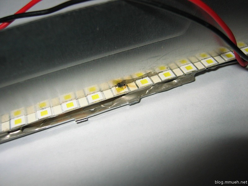
Defective LED
Bang!

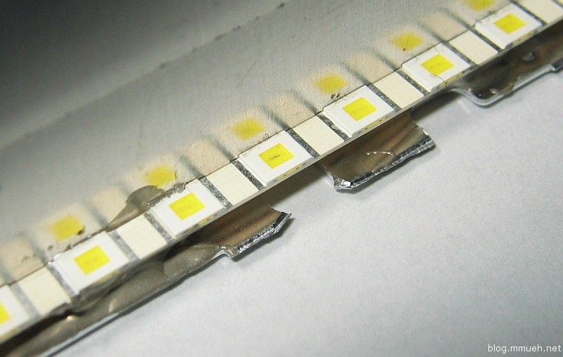
Defective LED
...and another.

Some days ago, one of the triple-chains on the right half of the screen went out. While the darker area is clearly visible, the shadow is still illuminated by the neighboring LEDs. The cause is the LED in the second picture, the damage is only visible as a slight dark streak in the center of the yellow part. Then today the backlight fuse blew out of this world, and the reason is seen in the first picture. I knew this was a close call, but precisely “calibrating” the almost not existent isolation gap between LEDs and metal (by wedging a piece of paper in every here and there during glueing :-D ) gave me no no reason for concern. Maybe some flexing or thermal deformation did the rest.

Anyhow, got to rebuild this part. Not too bad though, the stripes are inexpensive and I wanted to include a diffusor sheet anyway. As good a chance as any I guess.

Edit: By the way, the driver circuit survived the whole mess just fine. That IC is some tough design! Haven’t managed to fry a single one of those so far.