Here go the measurements. I use RMAA 5.5 free to do these.
All measurements were taken off an 5R6 load resistor. The maximum output power reached at 1 kHz sine into 5.6 ohms was 2.49 Weff resp. 4.97 Wpk, which is right on the money. Soft-clipping occurs right above that. I am not yet satisfied with the rise above 20 kHz, which I suspect to originate from a missing bypass cap in parallel to the feedback resistor. The cap short-circuits the feedback resistor at high frequencies to prevent oscillation (which currently occurs at 30-50 kHz when the volume isn’t turned all the way to the max).
The 50 Hz spike, on the contrary, is lower than I expected as I didn’t bother placing the output transformers away from the power transformer or putting them at an angle to prevent the magnetic fields from interfering. Another of those times when function follows form. Shielding in the wiring compartment could be improved a bit, though. Dunno if I should really photograph this mess.
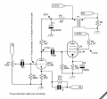
UPDATE: And here comes a screen of the schematic. No need to do it in EAGLE as there is no PCB, the whole amp is air-wired. Enjoy.
The usual word of warning: This circuit operates at voltage levels of >= 275 Vdc at relatively low supply impedance, so please be aware that you build this circuit at your own risk, and proceed with caution! I am not responsible for any damage/injury that might occur related to this circuit.
As I already mentioned, there are lots of parallels to the linked amps from the last post. A few annotations concerning the schematic:
- C5 is still missing in my case, estimate by trial and error.
- Some parts dissipate a noteable amount of power, as marked – choose for at least 2W of dissipation to be on the safe side. You might want to oversize a bit here, to minimize aging of the parts due to thermal stress.
- The coupling caps C3,C4 should be designed to handle voltages > 300 Vdc at least.
- R9 is the loudspeaker, of course ;-)
Another piece of advice I learned during testing: If the connected audio source device is somewhat valuable, it is wise to install a suppressor diode directly across the input in such a way that is shorts high potential at the input to ground. In case any high voltage potential gets through the capacitor in form of a spike (like it did through a damaged socket in my case), this will at least save your soundcard a lot of undue stress.


very good project ;i love it! congratulation