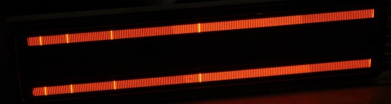
I picked up some unusual plasma displays from ebay some weeks ago, which I have been searching for quite some time now. The picture above shows an illuminated Burroughs PBG-12201 plasma bargraph display. They are pretty hard to get by now, and if available, prices are a real shocker. Some shops in the US that carry them ask for 230 USD and some even more. Sometimes they appear on ebay for about 50 USD, but you have to be real quick to get some. Best chances are with surplus stores that sell off leftover production stocks or disassembled devices that originally contained such tubes. A few very retro and very popular mixing consoles for audio applications used them as main VU meters (eg. made by Lexicon), as well as some current professional grade standalone meters (eg. RTW, one of those is where I first saw such a display and was absolutely fascinated by the deep orange hue). As they eventually get old and start flickering or burning in if not properly cared for, spare parts have become rare, and since Vishay – the most recent producer of these displays – has discontinued the product line in early 2012, I would expect the market to dry up even more.
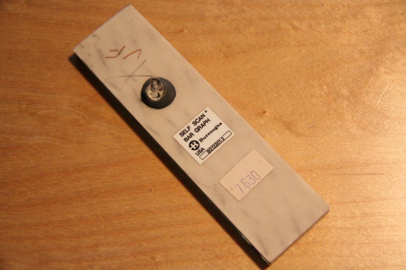


Mine were obviously scavenged from some kind of device by a Hungarian ebay seller, he offered some 10+ pieces of the PBG-12201 type display for 8 Euros each – a real steal! I just couldn’t resist and got myself three of them, together with matching sockets. Thinking back, I don’t get why I ordered three instead of four…oh well, it’s done. The tubes show some signs of wear, like glass chipped off around the edges and burn marks on the cathode traces, but they all work fine.
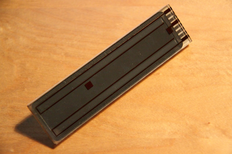
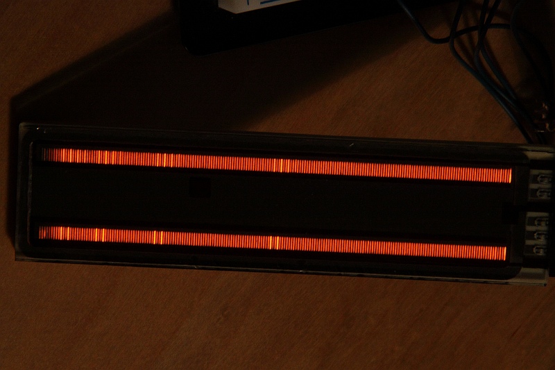
Devices like these use an interesting driving technique (from a retro point of view, today it is more of an old hat) as they are linear dot scanning displays – and befitting, the trade name for them is “Self-Scan”. The basic structure resembles a nixie tube: An evacuated sandwich made out of a glass plate and a ceramic back plate is filled with neon gas that can be ionized by applying a high voltage between a transparent anode metal film on the backside of the glass front plate and some printed cathodes on the back plate. However, this is a linear display, so it doesn’t consist of numbers but instead of small lines that have been masked by some isolating grey lacquer applied on top of the conductive traces. The left-out spaces in the mask form the slightly brighter active areas where the neon glow will appear. All in all, the tube provides two independent bargraphs with 201 segments each.
There even was a cool circular type of this display, but I don’t think there is any recent production of those.
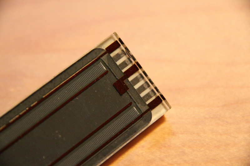
The port at one end of the tube features connections for:
- A pair of standby keepalive electrodes (Anode/Cathode) that are placed opposite of each other on the glass and ceramic plate. These are permanently lit up to keep a level of ionisation and never let the tube supply idle.
- Two independent anodes for the two bar strips.
- A reset electrode (actually the first strip in the bar)
- Three connections to an interleaved network of fine traces on the ceramic plate that are used to control the length of the bar. These cathodes are laid out to form three phases, meaning the 1st, 4th, 7th, etc. dots are connected to each other. As are all the dots shifted by one upwards, e.g. 2nd, 5th, 8th and so on. Finally, the same goes for the 3rd, 6th, 9th, etc.
To control the length of the bar, a rotating three-phase signal is applied to the three electrode combs. The comb corresponding to the currently next segment is switched to ground using a high voltage capable transistor (MPSA42 or comparable) and thereby “pulls” the glowing dot one step forward, then the connection is broken and the next comb in turn is switched to ground. When the end of the bar is reached, the phase signal is reset to the first phase and the reset electrode is pulled to ground for a fixed period of time. This extinguishes the glow and reignites it back at the first bar of the display. Only one electrode is glowing at a time, which gives the display a very precise scale and (in my opinion) makes it much more appealing to the eye than any continuous-glow linear nixie, like for example the IN-13.
Just to have covered the fundamentals: If you would slow down the scanning process of the display – which you actually can as the display is VERY tolerant of SLOW scanning times) – a single dot would travel the length of the bar. Persistence of vision (the slow recovery of the retina) makes this scanning process appear as a bar if the scanrate is high enough. Today, it is called multiplexing and used extensively in LED matrix displays. This also explains the missing-piece phenomenon in the second picture: Imagine the shutter of the camera opening while the dot wanders from 2/3rds of the bar to the end, wraps around and runs from the beginning up to 1/3rd.
A bar of varying length can be displayed by running the glowing dot up as many steps as needed, then resetting the display and starting again. There are specific minimum times that need to be maintained for phase on-time and reset on-time, so the display won’t start to flicker around erratically. One can achieve “frame rates” of up to 70 Hz for these displays according to the datasheet, which makes them flicker-free. My first attempts showed that there is some margin to the values, so experimentation is definately useful. Even more so if some of the dots should be of varying brightness. The way to achieve this is actually described at some point in one the datasheets if I remember correctly, but the principle is the same as when scanning LED displays: on-time control for each dot). In the pictures I have highlighted some random bars, this could certainly be used to make a scale. Unfortunately, the scale can only be visible in the lit-up area of the bar, because the display does not allow dark-scan to the point a scale mark is wanted at. Remember, the glow follows the grounded electrode – we can’t really make it jump across multiple bars, can we.
Also, there is some ghosting of the highlight marks because I drove the display with only about 180V dirty unfiltered DC with some serious ripple on it – probably as many as a few dozen Volts – where it typically needs about 250V pure DC to run. Well, it can’t be helped for now until I manage to find a matching ferrite for a step up supply in the depth of my boxes, so I used an old cheapo EL foil inverter I had lying around.
Maybe there is a possibility to scan the dark parts of the bar super-fast if the operating voltage is high enough, but I can try that only after I construct a proper supply.
I am currently driving the display from a simple breadboarded test circuit around an ATMEGA8 MCU while the high voltage side is handled by four MPSA42-transistors that I still had lying around from some recent audio power amp repair job. Note that I have not used base resistors, since the datasheet rates these transistors for Ib,max=100mA. While this is quite reckless to the chip and the transistors, it usually works for a crude test – a typical case of the “don’t want to walk to the basement and get some”-disease. Even so, it’s a no-no in proper designs. Collector resistors are not needed for the phase drivers because the current is limited by anode resistors already. The anode voltage is generated by said battery EL inverter which outputs about 150V of far-from-sinusoid AC, which I then one-way rectify using a single HV diode of a rectifier bridge to obtain about 180V DC. This is just sufficient to make the display ignite, but it causes severe troubles with stability. Misses a beefy cap.
EDIT: As usual, found a cap that I was looking for all over the place just when I had finished writing. Scavenged from a photo flash unit, 330V at 100 µF, plenty of charge. While the supply is still far from perfect, it does help to smooth the DC some. Enhances the risk of a painful encounter, too. This fixes most of the trouble with the bar for the moment, see the added a picture above. I will try for some daylight-comparable shots tomorrow.
In the link section below is a link to the official application note by Burroughs, which explains all the details of the drive circuit and also the possibility to drive the display using logic only. It’s nothing complicated really, but using a microcontroller brings all the advantages of being able to control precise on-times of each dot indepentently, so I guess that’s the way to go.
The next step will be to make a proper schematic and board for this with a proper supply and some analog or digital audio analysis circuitry and/or a digital control input. One of these would look great in the front of some big DIY amp, maybe behind a piece of smoke-colored acrylic or tinted glass :-)
Some background info and other projects for this kind of display:
Stereo-Balkenanzeige mit der Anzeigeröhre PBG12201 @ www.jogis-roehrenbude.de (German page)
Vishay PBG Plasma VU-meter…photos @ www.groupdiy.com (English forum thread)
PLASMA PBG12201 VU KITS @ www.groupdiy.com (English forum thread)
PBG display datasheet @ www.vishay.com
PBG display datasheet @ www.alldatasheet.com
Burroughs PBG application note no. BG101C @ www.brianroth.com
Hallo Mario,
die “kleinen” RTWs sind oder waren in der 1000er Serie verbaut.
Anbei Link zum Hersteller. http://www.rtw.de/uploads/media/RTW_Pi_Series_1000_E.pdf
Dort findest du nähere Angaben zu diesen PPMs.
Schönen Gruß
Oli
Hi Oli,
danke für die Antwort! Ich fürchte, ich habe mich falsch ausgedrückt – ich meinte eine Beschriftung/Typennummer auf den Displaymodulen selbst, wie sie in den RTWs stecken – nicht den Typ vom RTW ;-) Mein Fehler.
LG Mario
Da hast du dir aber schon gut Gedanken dazu gemacht.. Ich glaube, dass ist auch genau das, was mir so vorschwebte. Ich bin leider mit gar keinem uC firm, ich bin eher der Geisteswissenschaftler. Was Elektronik angeht, eher “Bastler” :), bzw. ich will mehr als ich es kann.
Damit du mal siehst, was mit den Anzeigen so geht:
http://waltpolitik.powerbone.de/radiodar/radar652.pdf
Ich denke, man sieht wirklich schöne Unterschiede, von rot zu orange bis gelb, fast weisslich.
Achso, wenn du wirklich vor der Anzeige von analog nach digital wandeln willst, müsstest du 4-fach Oversampling benutzen, um die sog. “intersample peaks” auch zu registrieren – das haben die herkömmlichen Peakmeter meist nicht und somit bekommst du u.U. deutlich falsche Messergebnisse.
Dazu kann man auch Einiges googlen.
Ich denke dein “hochgezüchtetes Peakmeter” soll mit digitalen als auch analogen Signalen gefüttert werden können? Dies gäbe es so auf dem Markt auch noch nicht :)
Alles in Allem ein richtig tolles Vorhaben, dafür bekommst du auf jeden Fall meine Unterstützung. (sag Bescheid – ich helfe, wenn ich helfen kann ;-) )
Merci für die Hinweise, ich melde mich wenn es weiter geht :-)
Die Farbunterschiede auf dem Bild sind ja wirklich heftig! Ich vermute zwar, dass der Weissabgleich von der Kamera da etwas reingepfuscht hat, aber ich sehe immerhin keine Farbfilter vor der Röhre. Das lässt ja hoffen!
Intersample-Peaks sind mir bisher noch nicht über den Weg gelaufen, ich werde mich da mal etwas einlesen. Alternativ könnte man den Bereich zwischen zwei Samples sicher auch interpolieren um die Spitze zu erfassen, aber präzise wird das nicht. Typische ADCs unterstützen ja in der Regel auch Samplingraten bis 192 kHz rum, mit einem internen Oversampling von bis zu 128x oder 256x. Dummerweise bringt letzteres für die Messung nix, da die Zwischenwerte ja intern schon ins Signal reingeschmiert werden, und am Ende trotzdem nur 44k Samples rauskommen.
Werde mal nachschlagen, was so ein DSP da hinbekommt.
Hi µ,
herzlichen Dank für deine Rückmeldung!
Das wird wohl sehr schwierig, ein Ersatzdisplay für mein RTW zu finden.. Evtl. frage ich mal bei Vishay direkt nach. Was mich auch wundert, nirgendswo im www kann ich den entsprechenen Typ, zumindest nicht von Vishay, finden.
Auf das Problem mit der Länge bin ich zufällig über Google-Bildsuche gestossen, als ich ein Bild von dem Display in einem russischen Forum mit Lineal daneben sah, war ich mir schon fast sicher :(
Hättest du Lust, ein quasi-RTW mit dem Display zu basteln?
Mir schwebt da ein, mittels µC/DSP einstellbares, multifunktionelles Teil vor, was es so auf dem Markt nicht gibt (einstellbare Integrationszeit/Rücklaufzeit, Peakmemo, Peakhold(direkt während der Anzeige des Signals als “dot” – geht sowas überhaupt, da ja “glow transfer principle”?), parallele Anzeige von bspw. Loudness/Peak mit helleren/dunkleren Segmenten, und und…
Spannend wäre hier auch, dass man nach dem neuen (digital) Standart “True Peak” messen könnte, der nicht wie bei der “QuasiPPM”-Messung (RTW’s) das Signal mit dem Leistungsfaktor 0,707 multipliziert (entspricht RMS, aber nur für reine Sinussignale – nicht bei Musik & Sprache), sondern die reine Spannung misst (Faktor 1) (Integrationszeit 0ms).
Mit den gebrauchten RTW’s von Ebay bin ich jetzt vorsichtig, kein Mensch weiss, wie lange die schon gelaufen haben und Ersatz gibt es ja nicht. Logisch ist ja auch, dass die ersten Segmente am meisten leiden..
Wäre doch klasse, wenn man so eine Schaltung auf die Beine stellen könnte, ich hätte da schon einen schönen diy-amp, den ich damit bestücken würde ;-)
Bei dem Preis der BG12201 überlege ich mir auch 3,4 zu ordern ;-)
Beste Grüße und Kompliment an Dich und deine Seite!
Alex
Alex,
mein Plan war ursprünglich, ein etwas hochgezüchtetes VU-Meter damit zu bauen, daher wäre das nicht weit ab vom Ziel. Was dem Ding dafür wirklich fehlt ist eine Textanzeige…weiß nicht, ob du es mal gesehen hast, es gibt ein Bastelprojekt, das ein sehr komplexes Meter mit einem VFD darstellt:
http://www.jogis-roehrenbude.de/Leserbriefe/Uwe-Beis_Pegelmessgeraet/DPLCM-VFD.htm
Mir geht es aber auch eher um die Leuchtfarbe vom Plasma ;-)
Da ich das Display noch nicht mit der vollen Anodenspannung betreiben konnte, weiß ich nicht, wie weit man die Helligkeitsdynamik wirklich ausreizen kann – aber deutliche Unterschiede sind definitiv drin. Sieht man ja auch gut auf dem Bild. Ein Peak-Marker ist allerdings ein Problem, weil ja der Balken zwischen RMS und Peak idealerweise dunkel wäre. GANZ dunkel wird voraussichtlich nicht gehen, da der Plasmapunkt irgendwie gezogen werden muss.
Ich hatte bisher auf der Liste:
Soweit dazu. Was mir noch nicht klar ist, ist der Mikroprozessor. Ich bin im Moment firm mit den AVRs von Atmel, die für solche Echtzeit-Rechnereien zu schwach sind, und mit den TMS320-DSPs von TI, die eher das Kanone:Spatz-Verhältnis darstellen. Da suche ich aktuell noch was Brauchbares. Vielleicht so einen PSoC von Cypress, die bringen anscheinend diverse Hardware-Bausteine für Signalverarbeitung mit. Je nach Typ ließe es sich vielleicht auch irgendwie erreichen, ohne Umweg über die analoge Schiene ein Digitalsignal á la S/P-DIF in die Messung zu schaffen. Das wäre in einem Amp jetzt eher Wurscht, aber für ein Standalone-Gerät sicher ein nettes Feature.
Ich hatte vor, auch eine Backpack-Platine für das Display aufzustellen, so dass sich das kompakt unterbringen bzw. irgendwie leicht nachbauen lässt.
Im Moment bin ich allerdings noch mit einigen anderen Dingen beschäftigt, März/April wollte ich mich dann mal näher mit den Plasmas auseinandersetzen und sehen, was so möglich ist.
LG µ
Hallo Alex, hast Du noch Interesse an Bargraph-Displays?
Ich hätte das eine oder andere Display abzugeben. (verschiedene Abmessungen, 3er oder 5erTakt)
Passen garantiert in RTWs!!!
Bei Interesse melden.
Gruß Oli
Hi µ,
schöne Displays, diese P/BG12201!
Ich habe ein defektes RTW 1119E zuhause, bei dem die ersten 2 Segmente jeweils ziemlich ungleichmäßig leuchten (eingebrännt, Glas rundherum dunkler).
Der Ungar bietet bei Ebay wieder die BG12201 für 8€ an, jetzt müsste ich aber noch wissen, wie lang die 2 Balken sind. Es gab nämlich eine Version mit schmäleren Segmenten (106mm Länge) und eine mit breiteren (127mm Balkenlänge), diese Version bräuchte ich.
Kannst du mal nachmessen?
Beste Grüße,
Alex
Hi Alex,
sicher doch :-) Vom ersten bis zum letzten Anzeigesegment sind es bei meiner Variante 102mm, das Deckelglas insgesamt ist 116mm von Kante bis Kante. Wenn man die rote Anodenspur mitmessen würde, wären es gaaaaanz großzügig die 106mm. Ich schätze mal, dass da durch die verschiedenen Herstellungstypen ein bisschen Schwund drin ist…
Ist also leider eher nicht die von Dir gesuchte. Ich habe mich allerdings auch schon gewundert, das RTW was ich mal in den Fingern hatte war ebenso eindeutig breiter als meine Displays!
Was die ersten Segmente angeht ist es bei den gebrauchten Teilen ein bisschen Glücksspiel. Ich habe drei mit unverfärbtem Glas und sauberen Segmenten bekommen, nur bei einem flackert das allererste Segment manchmal ein wenig im Betrieb. Scheint mal etwas überbestromt worden zu sein.
Viel Glück bei der weiteren Suche!
LG µ
Hallo Lordicewind
das 102mm Display ist die kleinere Variante.
Die RTW Standards sind 127mm groß.
Ich könnte sicher noch das eine oder andere besorgen.
Bei Interesse bitte melden
Gruß
Oli
@Oli: Danke für das Angebot, aber ich bin momentan versorgt. Aber gut zu wissen, dass mich das Augenmaß nicht getäuscht hat – ich hatte neulich ein RTW in der Hand, und dachte mir noch, dass die Maße irgendwie doch nicht so ganz zu den 12201er-Displays passen. Hast Du zufällig eine genaue Typennummer von der RTW-Variante? Würde mich mal interessieren, ob man dazu ein Datenblatt findet, bisher war mein Erfolg da lausig.
LG Mario