I remade the linear bearing sleds today, the previous ones were not precise enough – they were only the proof of concept anyway. The new ones glide on the rails as if they were not touching at all, VERY nice feeling if you lean on the bridge support with approx. 10 kg and slide it back and forth. No bumps, just smooooooooth metal! No clue how precise they are in terms of height differences and imprefections though, but there is a little potential to adjust if something should be too far off.


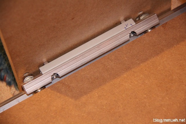

The portal looks very good so far! BUT….the cross-bar is skewed -.- Not by much, only one or two degrees around the length-axis, but it is enough for the right bearing sled to not sit on the rail properly. I can force it on, of course, but that is not the great idea here as the sleds should fit snugly on the rails without any force besides its own weight applied. In the beginning MDF was planned for this part, but I settled for beech wood instead. Best option here is to dump the current one, buy a precise MDF cut tomorrow and stuff the beech back into the scraps box for some future case build. After that, if the dimensions and angles of the portal as a whole are within tolerances, two more bearing sleds are needed to keep the portal on the rails while moving and when milling action occurs. Two more of the exact same type should suffice, but maybe some kind of spring-loaded mount would be better for long-term stability.
The side supports of the portal will be redone after the mill is completed. As will some other parts, probably. I will have access to a cnc mill then, so why not do the holes and cut-outs a little more precise ;-)
Hello,
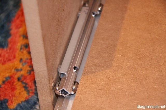
Your concept is very interesting! But I relly want to see the surface contact of the bolt head inside the square tube. Do you use a special piece to fit with the angle corner?
Thanks! Nice work!
Hi,
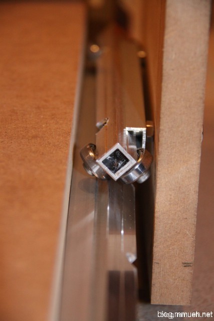
I’ll try to upload a good detail photo later today. The bolts are 45° countersunk screws that fit perfectly into the 90° angle. Currently, there is no fitting piece in between the bolt head and the tubing, so you can’t tighten the bolts with maximum force or the square tube will get deformed. That much wasn’t necessary so far, the assembly is quite sturdy. Also, the C-profile that holds the tube would be spread open by such a force.
A fitting piece would be a really good addition though. At least some kind of L-shaped aluminum profile spacer that keeps the bolt heads from contacting the tube. I think I’ll try that when I remove the rails for finishing and deburring the holes.
…and the promised detail shot (clickable for size). I used a different part that isn’t riddled with bearings, but the principle is the same for all.