A few weeks ago a friend brought me an old subwoofer that was discarded as broken – a JAMO SUB-660, which is an 600W sub for home cinema with integrated amping. The sub receives pretty good reviews, so I set out to try and fix it. I have worked on quite a few power amps until now, but as fully switched designs like this rarely fail, it is always a challenge when they do.

The most immediate symptom of failure was the absence of blue light on the front indicator ring. However, the fuse was not blown, and line voltage present at the PCB input. This already hinted heavily at the circuit, but for good procedure I also checked the sub impedance and amp outputs for shorts – all ok. Before I go into details, a word of warning because this beast managed to bite me even though I am pretty careful in my way around high voltage.
SMPS and Class-D amplifiers operate at line- and high DC potentials of up to 340VDC. Combined with the large stored charge, a discharge can kill or severly harm you even when not plugged in! Before you attempt to imitate anything written in this article, please reflect on your abilites!
Now let’s take a look at the design first. The presence of large ferrites with the typical tape-wrapped look on the PCB makes the supply a switched-mode PSU. However, there is no amp stage immediately visible. That is, until we look at the two odd transistors, which are mounted against the backplane right in between the preamp and main PCB. The markings make them out to be a pair of IRFB4227, which are real workhorse FETs in terms of high current switching. Minor cooling through the backplane and a highly integrated driver stage (SMD on the bottom layer) make this a digital Class-D amplifier stage, which operates very efficiently. The large wire-wrapped toroid to the left of Fig. 1 is part of the output filter which removes residual high-frequency ripple of the pulse-width modulation used for driving the output stage. All in all, a rather modern design, although it looks a bit cheap with the irregular assortment of parts and lots of glue poured all over the place. You can find some more background info on this particular module in a very helpful (german) forum thread:
http://www.hifi-forum.de/viewthread-225-2504-2.html
Basically, people there are discussing regular failure of these amp modules, as well as remedies for the various causes. The whole module was seemingly designed by Monacor, named SAM-300D, but has either been tuned or over-specced somewhat to make 600W on the paper. Most of these modules seem to fail due to shot-through secondary rectifiers in the primary supply, which then kills the gate driver and FETs in consequence and indicates that the power figure is rather optimistic. This failure is rather easy to fix, but made difficult by the fact that both SMPS driver ICs have been scraped clear of markings at the factory. Not a very nice move, but every now and then somebody forgets to grind. The guys from the forum have identified such cases, making out the two unknown ICs.

The amp is powered by a high-power SMPS stage which uses the bigger of the two wrapped ferrite transformers to produce something like +/-80VDC for the amplifier. The smaller one next to it is part of a secondary supply which delivers +/-15VDC to the standby circuit (just a single opamp, really), which in turn enables the big SMPS via opto-coupler once audio signals are present. After checking the rectified line voltage – 340VDC – I started with the standby voltages which should be present on the small three-pole plug connected to a gray flat ribbon cable. I found +/-6VDC, with a lot of fluctuation. At this point I pulled the PCB from the backplane to access the drive circuitry on the solder side. The drive IC has fortunately been identified already by forum users as a LNK624DG. Turns out this small 7 pin bug is actually pretty rugged and secure, and seemingly working perfectly well – except for going into protect mode almost instantly after power on. I then disconnected and checked its secondary load using a lab supply, but everything was fine. However, the positive-side rectifier diode was not. It was shorted, leading to 100kHz AC output into the caps. The caps short the AC out as intended, leading to a constant overload condition. Through feedback, the IC senses this and enters a pulse-sense-pulse state to try and restart (see LNK624 datasheet for details). I am actually rather impressed by its overcurrent protection, since many simple gate-driver based SMPS – like the big one in this module – are left to run unprotected and simply blow up from a shorted secondary.
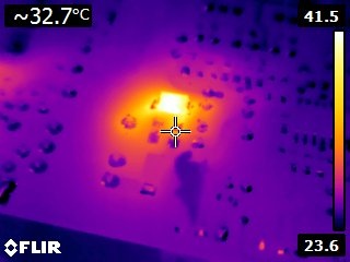
The diode (SMD Vishay SS16) was quickly exchanged for an equivalent device, but the supply still would not turn on. Checking with a thermal imager showed high temperatures on both diodes, even though both are Schottky types with low conduction loss. Two diodes in series brought an improvement here, which is due to the doubled reverse breakthrough voltage. Apparently, the replacements were not rated high enough – as were the originals!
However, the supply still would not stabilize, now flickering at around half the nominal output voltage. I then applied DC voltage from a lab supply to the SMPS input and slowly ramped that up. At around 15V the standby supply started delivering nominal output, but at around 180-200V it suddenly begins pumping and breaks down again. After checking everything else and even replacing the driver with a slightly more powerful LNK625DG, the only suspect remaining was the transformer. Unfortunately, I cannot measure the in-circuit currents safely with my current scope equipment, so visual inspection must be enough. On the other hand, transformers seldom break without any visible side-effects.
Disassembling transformers is not my favourite and usually senseless, but in this case it actually revealed a fixable problem in the form of a cracked ferrite. Now, that is a first – never had that before. A broken core does not have to be a problem by itself if the crack remains closed. However, this core was intentionally gapped in the center of the double-E, and this gap could close due to the lack of stability, which might have been one of the causes for the driver IC shutting down.
The reason is that a very low-power SMPS driver like the LNK624 only drives the core into one magnetization direction with its single-ended output stage. This leads to an non-zero average flux in the ferrite material, as opposed to bidirectional drive also known as push-pull. Not a problem if it’s done right, but it must be avoided to saturate the core by exceeding its material-dependent flux limit. If this happens, the flux will no longer increase with the coil current, and hence, the inductance will suddenly drop. As SMPS drive currents are usually slew-rate limited by coil inductance, the current rises fast. To avoid saturation, a bigger core could be used, which is somewhat wasteful. As an alternative, an air-gap introduced into the core can serve as an additional, non-saturable, magnetic material, which linearizes its behavior. The effect is comparable to the linearization of a typical diode I/V curve, where current rises steeply once the threshold voltage is exceeded. Here, one usually adds series resistance to enforce linear behavior. Thus, removing the gap from a gapped core can have the consequence of increasing flux above saturation. The drive current rises, which is interpreted as an overload condition by the driver IC. The resulting error would only appear when the flux is high enough to reach the saturation limit, which is more likely if a high drive voltage is available, making the drive current rise faster. All in all, a very unusual mode of failure which fits the circumstances. What was really unfortunate was the overlap between the effects of a weakened rectifier diode allowing reverse conduction and a brittle transformer.
The core is held in place by tape, which is removed easily, and a lot of soaking lacquer. A good trick is to heat the transformer to 100°C, which softens the lacquer and allows you to pull the core apart, gently! Especially the small ones are brittle as hell. Mine came apart without using force, since the crack was already there. Might be mechanical shock damage or caused by the bass. Do not heat above 100°C, as the winding insulation tape is usually PET or similar, which will soften and shrink at increased temperatures. After fixing the broken E with some glue and clamping the crack shut, I inserted a piece of plastic film exactly 150 micron thick to support the air gap. The exact spacing was measured from the outer dimensions of the core with a micrometer screw.

Note that removing the winding was not really necessary after all, but I was already at it and I wanted to try. My recommendation is to leave it, it’s really tedious work. I took down all turns numbers, alignments and wire gauges while unwinding, which is absolutely necessary for rewinding! I won’t go into detail here, except for some details about the transformer construction below. After reassembling the core and soldering the transformer, the driver had some starting issues at first – due to a shorted secondary, duh! – but after some resoldering, it started up nicely and the main PSU turned on as it should. Note that the LNK624 survived everything I threw at it without damage! Right now, I have the sub plugged together in a rather shaky state, but it works and plays along with my monitor speakers. The only thing which seems to have died from excessive unrectified AC is one of the opamps on the preamp board, which is singularly responsible for triggering the power saving mode. With this gone, the sub simply stays on. Going to save that for some rainy day.
The only downside is a slightly audible beeping noise from the transformer which I did not fix with lacquer – though it can’t be heard from inside the sub housing. A new core is required anyways, so I think I will make a new one altogether with the correct insulation material, to remove any remaining risks. For your benefit, here are drawings and winding / wire types. The base core type is probably Ee 16/15/5 or close, but I still have to measure its AL value to identify the ferrite material.
|
|
All windings are wound in the same direction, ends marked by dot. |
Now, let’s go over some additional things which I intend to fix at some point.
- In my revision (#2 according to marking) there is an additional single-diode rectifier path in the line-voltage side of the SMPS which is supposed to feed the standby PSU. The source can be selected by a solder-pad junction, but for some reason this was configured for the main rectifier and its large capacitors. This has the benefit of discharging the big capacitor bank over time (safety!) but leaves the small electrolytic of the additional rectifier – which has been built in – charged. Believe me, at 340V this little 4.7µF seriously hurts, especially with its connected traces easily touchable along the PCB edge and no discharge resistor. Fixed: Removed the rectifier diode and cap.
- You might have guessed it: Bleeding resistors for the big primary caps are marked but not populated. In my opinion, a faux-pas for any engineer! Fixed: Inserted 740 kOhms across the big Cs. 200-300k would be ideal, but at least the caps are now safe within minutes.
- From the forum, I gather that the secondary rectifier of the main PSU branch is too weak (1N/UF 5404). Paralleling two diodes is no durable solution, it would be better to use a single stronger diode, like e.g. MUR840/MUR860 which also has a better package for convection cooling.
- One of the two IRFB4227 had a large solder blob on its cooling surface, leading to a 0.5mm gap to the heatsink. Sloppy! Fortunately, Class D does not generate a lot of heat. Overtemp shutdown is not implemented.
My friend brought a JAMO SUB 660 in a “dead” condition with the fuse blowing repeatedly.Both the main PSU power fets (IRFP22n60k) are shorted as are the pair of IRFB4227 mounted on the back plane.
Any suggestions how to proceed before replacing the fets. Absence of a schematic is like a hit and miss operation.
Your suggestions/guidance highly valued.
Many Thanks.
Hello Noel,
If you need information write me on filip.pinzaru@gmail.com .
I can send you the list with components that I changed and made some upgrades also.
Read some info’s from here :
http://www.hifi-forum.de/viewthread-225-2504-2.html
Thank you !
Hi,
Looking at the effort you put in to refurbish the amp is impressive, I own a Jamo 250 which i not working at the pre-amp stage i notice there is missing component where a points to insert a transistor i couldn’t get a proper circuit diagram, Can you please share if you have an reference specific to jamo 250 subwoofer pre-amp.
Regards,
Vijay
Hi Vijay,
sorry for the late answer. Unfortunately, I don’t have any specific service documents. I had to conduct my repair from my own sketches of the circuit, too. There seem to be few documents available, with the only ones I found being for very old models.
Do you have some photographs of the PCB? Maybe that could help identify your missing part. If you want, pass them to me by email to admin@muwave.de.
Best regards,
Mario
Hello Mario,
I own a Jamo SUB660 too, but in the morning I started a movie and the sub started playing really hard and then just stopped (shut off) :(. The fuse is blown.
The volume on sub was about 1/4. On the receiver the volume was -7db. So….it should not be from too much power.
Now, it constantly blows fuses on every start-up.
What should I measure first ?
Thank you !
Hey Filip,
I am having the same problem since last week. Every fuse blows the moment it’s turned on. Let me know if you are able to fix or let me know if you have any alternative , it would be really helpful.
Thank you.
solved the problem with a blown fuse?