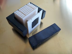
Getting a fitting transformer bobbin for ferrites is not easy under normal circumstances, but even more so for cores of unknown type. Usually, the dimensions follow a somewhat standardized pattern, but then your application might demand for separate winding chambers or mounting aids which are simply not available to the standard customer. So why not 3D print it?
The motivation is to use an old ferrite core for a high voltage lab supply. It will be driven far below its theoretical maximum spec as I only know it came from a ~50W power supply. My design (a flyback converter) requires a single winding in single-ended mode for the primary consisting of 23 turns, and a secondary of 235 turns capable of withstanding roughly 1kV. For winding I use standard enameled solid copper wire of unknown brand, which will probably not survive the full voltage. As a solution, I want to separate the secondary into 6 compartments of 40 turns each to reduce the maximum possible voltage between two neighboring wires to a maximum of 166V, which is well below the breakdown range. Without compartments, the left-to-right-to-left layer winding – which will occur somewhat naturally – may cause turns with extreme voltage difference to end up touching, leading to arcing sooner or later. To additionally strengthen the winding, a soaking resin could be applied.
Using the dimensions of the core as a base, some modeling in Tinkercad yielded this:
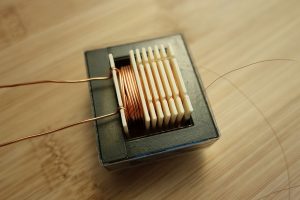
The bobbin prints a little tight, but with a few strokes of a needle file it fits a 13x13mm core perfectly. The separators are 1mm thick, both to ensure a leak-free buildup of the plastic and to allow my printer (.4mm nozzle) to print it. I tried .5mm width, didn’t work. The small recesses are for wire guiding. At this point, I screwed up during design – it is not so smart to align the feed for each winding with each other as this decreases the path length and thus increases electric field strength. It should be fine in this case – I usually calculate arcing distance as a very pessimistic 4-5mm per kV in air, and that is without the added enamel of the wires. The return wire is also shown without an insulating sleeve on the photo, I plan on adding some thin teflon tube to improve that. Have to get that first, though.
You can download the .STL as an example, though it will probably not fit your application. This might be a neat example for a parameterized model. I’ll see if I can write something. For printing, you best rotate the model such that the separators are standing vertical on the build plane with the notches upwards, and enable supports both from below and inside the model. At least on my Prusa i3Mk2, the supports come out easily after printing, with almost no finishing needed.
Remember to use heat-resistant material if necessary! I printed the bobbin in PLA since I don’t expect much heating. For high power, I would probably resort to PET or ABS, or even Nylon.


Is it safe to print a transformer bobbin with PLA ? (heat issues)
I would not use it for high-power applications as it is, as you rightly mention. In this case it is used as a low-power, high-voltage transformer, and the core volume and winding insulation strength are both overspecced. I did not have any heat issues so far. If you want to go for high power, you might want to print in ABS or fiber-reinforced filaments to improve temperature stability. Also, I would bet the isolation voltage is not nearly as high as you would get it with a solid plastic piece.