Recently, the speedometer of my trusty old Volvo 850 station-wagon started acting up. Initially, it would just drop to zero intermittently at speed, then come back. Hard to notice if you only so much as glance at it every now and then. Over the last two weeks this got worse such that it would only very rarely do anything at all. My best guess for the cause would have been the speed sensor at the vehicle underside, but for mysterious reasons the odometer was still going at the normal pace. According to the instrument schematics, this should not be possible if the sensor were broken – same signal for both. So, something else must be going on. After brooding over the schematics some more, I decided that the reasonable option would be to remove the dashboard cover and pull the instrument cluster, since this is where all relevant electronics are located. Note that my Volvo is equipped with a Fenix 5.2 (5 cylinder) motor control and therefore has the Yazaki instrument panel which receives the speed signal directly. Other models might get the pass-through signal from the ECU instead, which introduces another point of failure!
To remove the cluster, you first have to remove torx screws which are located:
- 1 each holding left and right window air duct (in doorframe, only accessible when door is open)
- 1 each under window air duct covers after removal
- 3 in glove box, along top edge
- 1 each behind vents in center console (tilt vent up, then tilt some more with force to remove it)
- 2 above instrument cluster
- 1 in left upper driver’s vent
You will also need to remove the left and right front speakers because they are cabled and also tend to snag at some structural parts. Carefully pry out the gratings (from the windshield side!), then remove two screws and pull up by the rounded metal tab. Undo the speaker cable plugs, then pull out the speakers. Now you can gently lift up the dash cover by its front edge, pull it towards you and carry it out through the driver-side door. The instrument cluster can now be accessed. Remove the two connectors by carefully sliding the tiny green locking tab facing the driver upwards towards the cable while gently pulling the plug. Now release the two snap holders, slightly tilt the panel away from you and pull it upwards. Take care not to break off the two plastic studs on the bottom which lock it in place! Unfortunately, I couldn’t take pictures during dashboard removal as I was doing that alone – not much free hand.

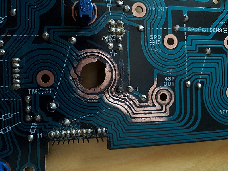
With the cluster in hand, the fault became visible immediately. A black, charred spot right behind the speedometer contacts looked like burn damage, but was actually acid corrosion judging by the way the PCB resist was discolored and flaking off. It turned out a cap right on the other side had blown out through its wire holes (not the lid!) and the acid had crept through the PCB solder joints, right under the resist. I found the same type of defect on the backside of the speedometer module – probably some acid vapor was deposited here. To make things worse, the speedo- and tachometer modules each had their own caps which were also leaky. The electrolyte seems to be of the old, REALLY corrosive type. The two caps found on the main PCB and speedo module were 100µF/25V types, so overvoltage is probably not the cause. My guess would be continued overtemperature in hot summers. The cap on the tacho module was 220µF/25V. I replaced all three with 220µF/35V types, but take care that the cap on the backplane PCB has to fit into a hole in the plastic mounting frame.
|
|
|

Cleaning of the PCB was done with a wet wipe, followed by abrasive cleaning of the corroded traces with a fiberglass pen. Do not stop until the copper appears clean, and do yourself a favor: wear latex gloves and wet the PCB before scratching. This keeps the fiber splinters away from clothes and fingers. When all the gunk had come off, I went for two more wet cleaning steps to remove all residual acid and an additional spray-down with an agressive electronics cleaner (a mixture of acetone, propanole/ethanole and some other stuff). Only stop the wet cleaning when a wet paper towel shows no more yellow-ish stuff coming off the PCB.
Afterwards, I repaired the defective traces by soldering thin tinned wire along the path. Take care to fix the wire with solder at regular intervals! I then painted the solder works with transparent fingernail lacquer, which is an excellent insulator and removed easily with acetone should the need arise.
A test drive confirmed that the speedometer worked again. The only thing which does not work completely is the right-hand backlighting of the speedometer. The bulb contacts were also damaged by the acid, which broke the lighting at some point. I originally suspected the bulb, but it worked fine after cleaning. However, some of the oxides must have been left over which makes the bulb a bit dim now. Oh well, another time.
Dear Mario,
thank you very much for this detailed explanation about how to repair 850 Yazaki cluster.
Do you have others pictures, especially of the capacitor polarity on speedo needle drive card ? If you have any, it will save my day !
Hi Jean-Pierre,
just checked – unfortunately not (yet). I didn’t think of that at the time because the majority of damage was on the backside.
However, I think could take some new pics sometime next week. I’ve wanted to change some broken illumination bulbs for quite a while, anyways.
Did the caps fall off entirely in your case?