I bought this used broken unit after covid, not really to solve any air problems but because I found the integrated sensors pretty interesting for the price. The Xiaomi air purifiers operate on a laser particle sensor to measure air quality, combined with a Sensirion SHT temperature/humidity sensor. The data are available over wifi via the smartphone app, which is rather not to my liking – especially hooking up such a reportedly unsafe ([4]) device to my network. That is something I wanted to change, along with fixing the motor. Well, a lot of time has passed, but now it’s actually happening.
I’ll try to add to the others’ knowledge wherever I can. I am currently writing my own custom software for the ESP32 with the aim of integrating the 3H into an MQTT ecosystem, but keeping out overhead like ESPHome or Home Assistant. I’ll push that to Github in the next few days when it’s finished – more to follow here. The code is written for the Espressif IDF toolchain, to be compiled in the Eclipse IDE. It uses standard libraries or openly available ones wherever possible, but also builds on Jaro’s code for the communications part. At a later point I also want to dabble at replacing the STM32 code. I should mention that this post series is not about dumping or modifying any original code or data, or about anything related to the cloud link, since all of that is most likely a waste of time. I’m not going to keep any linkage to the original cloud/app, but for the time being successively replace parts of the functionality – which requires me to figure out how things talk to each other.
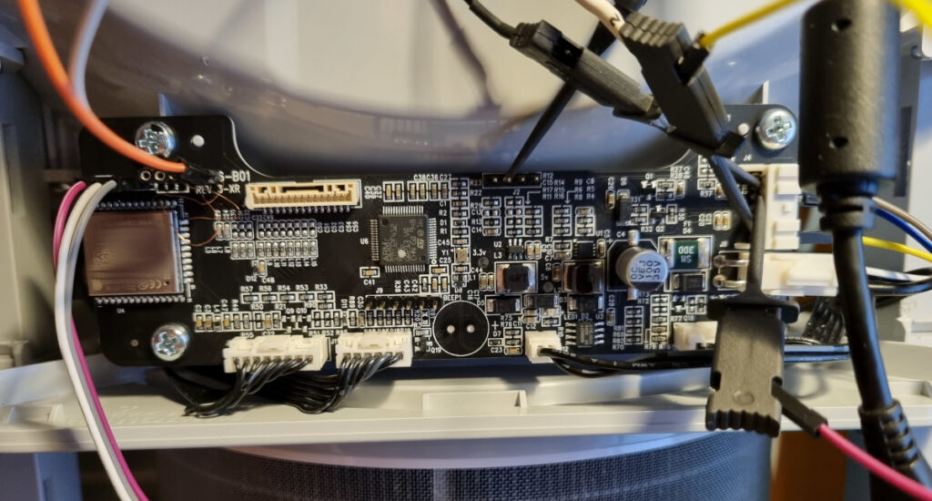
Before I start: A lot has already been done in the past years, so I’m kind of late to the party. Several people have hacked at this purifier series, as they have for many other Xiaomi devices (smart vacuums, etc). The RFID-chipped filter has already been unlocked to reset its hours [1], and parts of the internal circuitry (featuring an STM32 system controller and ESP32 as wifi node) have been reverse engineered, too [2-5]. I’ll add the links below. Especially the last one is very interesting, because Jaro Meyer has decoded part of the internal communication bus with the aim of reprogramming the ESP32 with custom software. This has been done by “The Flamingo”, who has provided an ESPHome-based Home Assistant integration [6]. In this case, the ESP32 is reprogrammed while the STM32 retains its original function. The communication protocol is partially described by Jaro in [5], see the protocol.pdf description in the Git repo. The connection points on the PCB are described extensively in [2]. I used a Logic8 to capture and decode the signals:

The basic protocol is simple – the STM32 acts as a bus master and issues reports on state changes or queries for the ESP to talk. The ESP either uses these periodic chances to issue its own data query, provides the appropriate data, or acknowledges whatever data it receives. The STM32 handles the state machine, sensors, fan regulator, UI and RFID. The ESP is its formal sidekick, only responsible for Wifi or BLE communications. It should be mentioned here, that the ESP (marked ESP32-WROOM-32D) is an odd one: It does not respond with a clear signature, but reports a single CPU core to esptool although this version should be a dual core. It also has no fixed MAC (although there is one laser-marked on the package), but uses the one issued to it by the STM32 after boot. Since the markings are also in serif font unlike typical ESP modules, this must be either a clone or a customized version.
As it appears, the STM32 is set up to provide two USART interfaces. One goes to the ESP32, while the other is broken out to pin header J2 on the PCB. While the first one carries the ping-pong communication to the ESP, J2 offers a debug interface. No idea if there are commands that can be written on it – but the STM32 sure is talkative, reporting in clear text on most things it does. By hooking up a logic analyzer to both ports, this is what a typical start-up sequence looks like on the debug bus:
####Enter Bootloader
Enter firmware_check
Enter check_boot_mode
PUBLIC_Debug_Init
XMAIR_App_Thread version:0009
PUBLIC_I2c_Init
PUBLIC_Beep_Init
AIR_Var_Default
#####Last Reboot cause 0,e000003
XMAIR_Sem_Init
get into XMAIR_Motor_Init
MOTOR_Clk_Init
XMAIR_Button_Init
Touch_Init
SHT Sensor Init
POWDER_Sensor_Init
XMAIR_DisplayInit
RFID_Security_Cal source: 4 xx xx xx xx xx xx (MAC blanked here)
RFID_Mfrc_RegGet failed to get mutex
XMAIR_PowerTimer_Init
g_enCpuState is 1
In parallel, this happens on the ESP bus (STM32 talking in green, ESP talking in red):
model zhimi.airpurifier.mb3\r
ok\r
ble_config set 1182 0009\r
ok\r
mcu_version 0009\r
ok\r
get_down\r
down none\r
As courtesy demands, the ESP spends most of its time nodding agreement. Every line in both directions is terminated by a CR character. The last query “get_down” offers a chance to say something (download), but at this time the ESP passes by responding “down none”, nothing to say. Some time after that, there follows an announcement of the MAC address:
properties_changed 14 1 "xx:xx:xx:xx:xx:xx:4" (MAC blanked here)
ok\r
After that, normal ping-pong exchange of get_down and corresponding responses continues. The STM uses a key-value-based parameter transfer scheme. Unfortunately, I did not get a chance to capture the bus behavior of the original ESP firmware, since my ESP chose to corrupt its firmware instead of dumping it to disk, which might be related to this ESP to be a weird sort of between-specs variety. Well, so there’s no way back now ;-) However, by Jaro’s recount there are usually two key values (e.g. “14 1” for MAC) followed by a numerical, boolean or string value element. This is actually not too hard to figure out with access to J2, because the STM drops irregular clear-text hints at what the format is supposed to be. The basic info packets for data query and button presses are straightforward, but I would have been lost at the keep-alive packets since I never got a chance to witness those. By the way, if the ESP fails to respond to the initial “model” announcement multiple times, the STM32 tries to reset it multiple times (command word “reboot”) before it stops on a “MODEL_NAME timeount” (no typo) debug message. It appears that the ESP is left for dead afterwards until a reboot occurs.
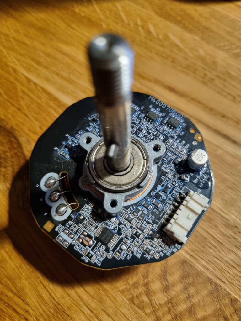
However, I could also verify (since my motor is broken due to a faulty controller IC) that the ESP communication continues even if the display shows an error message (e.g. “Motor error”), or if the display is not connected at all. For that matter, the motor can be spoofed easily by attaching a PC fan tacho signal or a simple square-wave clock to the FG pin on the motor port (e.g. generated by the ESP). If a PC fan is used, a 10k pull-up to 5V on the same connector should be added, since the open-collector tacho output can only pull the RPM pin to ground. As soon as FG changes its level frequently, the STM will assume presence of a motor and unlock. The signal does not have to match any particular speed setting. Right now, there are some matching 48F704 replacement motors made by Nidec available on eBay, so this might be an option.
References:
- [1] Breaking Free from DRM: The Story of Hacking My Air Purifier – Unethical Info
- [2] Xiaomi Air Purifier 3H Reverse Engineering Part 1: Probing Around – Flamingo-Tech
- [3] Xiaomi Air Purifier 3H Reverse Engineering Part 2: Fremont EEPROM dump – Flamingo-Tech
- [4] Xiaomi Air Purifier 3H Reverse Engineering Part 3: ESP32 DUMP – Flamingo-Tech
- [5] jaromeyer/mipurifier-esphome: ESPHome for the Xiaomi Mi Air Purifier 3H (and similar devices using the same protocol)
- [6] Flamingo-tech/xiaomi-air-purifier-reverse-engineering: Xiaomi air filter H3 reverse engineering