Running a EL640-400 TFEL display off the RPi native DPI/VGA interface

Following several somewhat successful tries to bit-bang VGA signals for TFEL displays I have moved to the integrated native display parallel interface (DPI) of Raspberry Pi models 2 and later [1][2].

By using this GPIO drive mode it is possible to offload framebuffer output to the hardware, which brings speed and saves a huge amount of CPU resources compared to bit-banging. This interface is frequently used for outputting VGA signals, since it is one of the original display signal output methods of the Broadcom CPU for driving parallel TFTs or LCDs. Obtaining analog VGA from it requires a resistor ladder DAC board [3], which combines the individual digital bit signals to analog multi-level RGB signals. In the case of a TFEL display this is not necessary, since the control circuit accepts digital level VGA. However, the clock mode is a bit unusual compared to the common configurations (as explained in previous posts: required is a 640×400 pixels, >70 Hz, monochrome signal).

Continue reading
VOLVO 850: Broken speedometer

Recently, the speedometer of my trusty old Volvo 850 station-wagon started acting up. Initially, it would just drop to zero intermittently at speed, then come back. Hard to notice if you only so much as glance at it every now and then. Over the last two weeks this got worse such that it would only very rarely do anything at all. My best guess for the cause would have been the speed sensor at the vehicle underside, but for mysterious reasons the odometer was still going at the normal pace. According to the instrument schematics, this should not be possible if the sensor were broken – same signal for both. Continue reading

3D-printed transformer bobbin

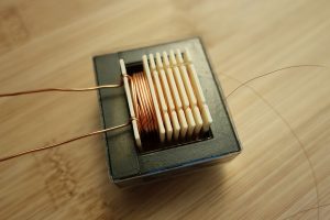
Getting a fitting transformer bobbin for ferrites is not easy under normal circumstances, but even more so for cores of unknown type. Usually, the dimensions follow a somewhat standardized pattern, but then your application might demand for separate winding chambers or mounting aids which are simply not available to the standard customer. So why not 3D print it?

The motivation is to use an old ferrite core for a high voltage lab supply. It will be driven far below its theoretical maximum spec as I only know it came from a ~50W power supply. My design (a flyback converter) requires a single winding in single-ended mode for the primary consisting of 23 turns, and a secondary of 235 turns capable of withstanding roughly 1kV. For winding I use standard enameled solid copper wire of unknown brand, which will probably not survive the full voltage. As a solution, I want to separate the secondary into 6 compartments of 40 turns each to reduce the maximum possible voltage between two neighboring wires to a maximum of 166V, which is well below the breakdown range. Without compartments, the left-to-right-to-left layer winding – which will occur somewhat naturally – may cause turns with extreme voltage difference to end up touching, leading to arcing sooner or later. To additionally strengthen the winding, a soaking resin could be applied.

Using the dimensions of the core as a base, some modeling in Tinkercad yielded this:

Tinkercad design ready for STL export.

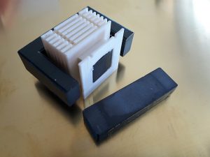
Finished print in PLA, filed and mounted on ferrite.

Windings inserted, ferrite closed and fixed with PET tape.

Continue reading

JAMO 660 subwoofer amp

A few weeks ago a friend brought me an old subwoofer that was discarded as broken – a JAMO SUB-660, which is an 600W sub for home cinema with integrated amping. The sub receives pretty good reviews, so I set out to try and fix it. I have worked on quite a few power amps until now, but as fully switched designs like this rarely fail, it is always a challenge when they do.

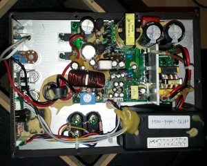
Fig. 1: Jamo SUB-660 power amp module. High-power PSU (right top), standby PSU (right of centre), Class-D amp (above centre) with large output filter choke (centre). Preamp, sound filters and standby detector PCB on the left, line input on the bottom right.

Continue reading

Running a Planar TFEL display off the Raspberry Pi GPIO

Fig. 1: Archlinux logo running on a raspberry-driven Planar/Finlux EL640.400 display.

Thin film electro-luminescent (TFEL) displays represent an interesting, if somewhat anachronistic display technology, now that we have high-contrast LCDs, plasma displays and of course OLEDs. The latter are actually closest to the principle of TFELs, and their primary optical advantage is identical: light-emitting pixels instead of backlighting, for maximum contrast. Where OLEDs use an organic polymer, which can be excited to emit visible light by applying an electric field, a TFEL does the same with an anorganic dielectric material like e.g., gallium arsenide (GaAs). The emitter pixels are sandwiched between two layers of transparent dielectric to insulate them from the transparent electrode grids on the front and back glass cover of the display panel. When a high-frequency current is applied, a current flows through the selected pixel and the emitter material lights up in a beautiful, saturated orange – in my opinion the most interesting aspect about this technology. Remember the old terminals with the amber CRT screen? Close! In contrast to OLEDs, EL displays are also able to tolerate much harsher environmental and mechanical conditions, which makes them ideal for applications in heavy machinery – or living room gadgets, when they are retired. Continue reading

Monitoring and controlling a JUDO i-Soft plus via LAN

Some time ago, a water softening device was installed in my home main water supply line. Such a device contains one or multiple gel capsules that act as ion exchangers, replacing calcium and magnesium in the fresh water supply with sodium. In regions with a rather hard water, this can save you a lot of trouble with maintenance of valves and the lifetime of water-consuming devices like washing machines and dishwashers.

Fig. 1: JUDO i-Soft plus unit with LCD touchscreen user interface.

For regulation, a conductivity sensor determines the hardness of the incoming water. After running through the gel exchanger, the residual hardness is assumed to be around 0.5 °dH which allows the mixing ratio of raw and processed water to be calculated. I won’t go further into details here, the bottom line is: It works like a charm, water is as soft as it needs to be. The device at hand is built by JUDO and is available in several configurations. Basic models contain a two-capsule exchanger for seamless switchover/regeneration cycles and an integrated electronic control unit for automatic regeneration of the gel. A more advanced “i-Soft plus” model is extended by a touchscreen user interface complete with LAN/WLAN network access. This enables monitoring through a specialized iPad application where the interested user can view total water consumption per day, week, month or year as well as change different system parameters. As a nice bonus, the plus unit has an integrated main line valve which is closed automatically whenever user-set time, volume or flow rate limits are exceeded. This already saved my ass once when a pipe became leaky inside a wall. Unfortunately, the exact protocol for communication with the device is not disclosed, which is where this story begins. Continue reading

HP 8565A: Sweep time selector

As I already mentioned, the highest priority fix is the input RF attenuator. To get access to this, the control panel must be taken out since the connector is placed at a slightly inconvenient place – the bottom of the motherboard. Unfortunately, right beneath this is the aluminum carrier plate that contains all the RF circuits consisting of semi-rigid coax and clunky metal-jacketed modules. I first unmounted the top, bottom and right side panels, which was an easy job:

  • Loosen the single screws at the back of top and bottom covers and pull them off towards the back.
  • Remove the two screws holding the carrying handle and pull off the side panel along with it.
  • Also remove the top and bottom plastic inlays from the front aluminum frame, these cover up the panel screws.
  • Remove all visible screws from the top of the frame that seem to belong to the right panel (should be 3) and also from the bottom (should be 2). Take care not to remove the 2 rightmost screws on the bottom, these hold the front connectors and are best left in.

Now pull the control panel right out.

IMG_1011_web
Fig. 1: Control panel removed from case.

If it sticks, the points to watch out for are the N-type RF connector and the PCB edge of the sweep time selector. Gentle pulling while wiggling the panel up and down some will bring it out. Remove all connectors from the backside. Don’t worry, the plugs can’t be interchanged. Set the panel on a flat surface, front side down (Fig. 1). Continue reading

HP 8565A Spectrum Analyzer

Originally I was looking around a well known auction house for a digital Spectrum/Network analyzer from one of the older Tektronix 2715 or HP8566 series to extend my measurement rack to higher frequencies, but they are hard to find for a reasonable price in relation to the risk of buying a device in unknown condition. Still, I wanted one of the older models, because of their excellent design and repairability. Maybe without the exception for some very special, custom parts – but we’ll just hope that those don’t break.

Also, in my understanding a slightly older system from the top series at the time still outperforms most more expensive, modern, all-digital-hey-we-compensate-all-the-errors devices. That is not to say that digital processing and compensation of systematic errors is bogus, of course! But at the same time, any weak measurement hardware can be made to appear top-class by taking several thousand complete sequences and averaging. Getting it right on a single try is an art for itself, and designing a combination of precise hardware and just the right amount of post-processing is the reason for the price. Or maybe I’m just a sucker for retro tech, with all its edges, heavy metal and shiny parts.

HP 8565A front
Fig. 1: HP 8565A running, showing a weak signal in the GSM area.

So, I finally got a fair deal on this 8565A unit. I might have wanted to choose its bigger brother 8569B instead, which has a wider external mixer span of up to 115 GHz and a digital control interface, but the LED readout certainly adds a special flavor to the set. The seller had informed me that the device would be uncalibrated and the sweep time selector didn’t work anymore. Usually such estimates contain some tolerance, so I already expected some other things that maybe nobody noticed. Since my original plan was to recalibrate whichever device I got anyway and fix all the problems over time, that would be okay. The fixes will be documented here. Continue reading

Sony TA-F220

These are just some short notes I took while inspecting an aged Sony TA-F220 amp some days ago. I have seen several of these over the last years, pretty decent amp with a nice sound. They all have some regular aging flaws in common, though.

f220_01
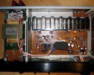
Fig. 1: Top-down view inside the TA-F220.

Continue reading