Workbench #2

So much for the current status of the CNC milling machine. I have made some first experiments with L297/298 motor drivers and found out the hard way that these are quite overloaded with such strong motors. Burnt out in a matter of seconds. But, as BJT driver bridges are not state of the art anyways, and I want to take a lesson from this project, I decided to finally get myself some of those specialized ATMEL controllers (AT90PWM1) and try to design my own FET bridge driver.

I even have one in spare that I can use for experiments with a self-designed high intensity discharge lamp driver – I have attached an image of an early prototype to the gallery for your entertainment. Worked quite well for some time, but the driving was very crude – there are some logic gates on the bottom of that small pcb that generate half-bridge signals for the two FETs, but no care taken about anti-shoot-through and so on. VERY crude. I will report how well the new controllers work out, seeing that very few experiences are found :-)

As for the CNC, I am quite confident that I will finish the mechanics part within the next holidays (around easter). Then, all that remains is the ‘intelligent’ part.

Last but not least, I notice that I still do not manage to describe my projects in my self-desired level of detail. Thus I will focus more on taking pictures during the process and explaining from now on.

UV pcb exposure box

Today, I want to write a few words about another of my older projects.

UV exposure box - whole view

A while ago, I started building this DIY UV exposure box. The electrical part consists of a self-designed count-down timer based on an AVR Tiny2313 CPU, 4x8W PHILIPS UV tubes, ignition/driver circuits from cheap fluorescent bulbs, a multiplexed numeric LED display, a rotary encoder and some wiring. A piece of ~4mm aluminum serves as a faceplate, picture frame glass as the exposure surface. We’ll have a look inside in a moment.

When turned on, the controller presents the configuration menu first. All options are preset – or should I say ‘preprogrammed’ because the preset cannot be changed, as of yet – to the values I use most frequently. Configuration includes the time (up to 9min 59sec), a variable tube preheat time up to 59 seconds and a zone selection. The zone selection does nothing at the moment, but the pcb features a mounting spot for a second solid state relais which I have not yet installed. Which means, all four tubes are activated.

Exposure box - menu
Minutes…

Exposure box - menu
Seconds…

Exposure box - menu
Zones…

Exposure box - menu
Preheat…

Exposure box - menu
…ready to go!

Exposure device - running
Enjoy

Press the selector one more time and the process starts. To stop again, either press the button again, switch off the mains or wait patiently until the time runs out.

Now, on to the inner values. After undoing 7 torx screws, the lid can be removed to access the elecronics compartment behind the front panel:

Exposure device - mains part
Mains input and ignitors

Exposure device - microcontroller
Microcontroller board

Exposure device - electronics compartment
Electronics compartment

Inside the compartment is the four-fold ballast circuit, which consists of four board found in the sockets of fluorescent energy saving lights. These are pretty cheap compared to commercial electronic or inductive ballasts and they can be used right as they come. The only crucial number is the power rating – my tubes are rated for 8W while the ballasts came from 9W bulbs, which works just fine. Care has to be taken when opening the sockets, though. The bulbs should be left lying around for some time prior to “dissection” because they contain a pretty juicy capacitor. The circuit inside is basically a simple switchmode current supply. When that’s done, an easy way is to cut them open along the circumfence about in the middle of the socket’s height with a fine saw blade. Don’t cut too deep or you will damage the pcb. Once the casing is open, mark the pairs of wires coming from each end of the tube before cutting them. These pairs need to go to the ends of the UV tube, don’t mix them up or you’ll short out the circuit. How the two wires connect to the two pins of the tube on each side is completely up to your choice, though.

As always, remember the hazards involved when dealing with mains equipment, especially such that was never designed to be opened or even run in the open. Also, don’t go breaking any fluorescent tubes as they might contain traces of mercury.

The four ballasts are wired in parallel to the mains, with just a fuse, the power switch and a solid state relais in series. Fuse-wiring got a little complicated because I forgot to place separate fuse sockets for controller and drivers onto the pcb, but nothing dangerous here. A connection between faceplate and protective earth is also present for safety reasons, seeing that there is lots of live wiring very near. You may have noticed the absence of any cooling fan or holes – these are not necessary as the device is run for a few minutes at a time and never unobserved. The ballast circuits are designed for operation in a very tight unventilated space anyways, so no trouble to that end. After ~5 minutes of exposure the glass surface becomes just noticeably warm.

To the right is the control circuit, consisting of said ATTiny2313, a small 6VA transformer-powered 5V supply, the solid state relais (SHARP S202S02) and three npn transistors as segment drivers for the LED display. I still have some pictures from back when I made the pcb (about a year ago now):

Drilling holes…

Finished pcb

…all soldered.

I have used this exposure box several times now and am pretty content with the results. There still remains some creepage of light between the layout print and the photosensitive layer, resulting in fuzzy edges of traces and larger groundplanes sprinkled with small holes. This is partly thanks to an absolutely ridiculous laser printer made by HP (Color LaserJet 2600nse). No matter what settings are used (even in the expert options), the printer will never do dense black withing planes and very often blur traces on either the leading or trailing edge. Text works fine, though.

You may download the schematics in Eagle 6 format at your leisure. I do not guarantee correctness of the layout, though. There was a small problem in an earlier version (Pin 1 of ribbon cable connector was not connected to ground) which I have fixed now.

I do not take any responsibility for whatever happens to you. It’s up to you to decide if you want to and are able to build something like this.

>> EAGLE 6.0.0 Schematic and Layout

>> Script files for older versions of EAGLE – untested!

>> Sourcecode and .hex for ATTiny2313

* NOTE: Make sure that pin 1 of the front panel connector is really connected to ground, the traces were etched away in my case. The result is erratic behaviour of the rotary encoder.

CNC update

Alright, time for another update linked to the CNC mill! I just finished the linear carriage for the X-direction. Still having some minor trouble getting a tight fit between the bearing-rollers and the rails, but I suspect this will be correctable later through adjustment. The whole thing needs to be carefully calibrated and aligned anyways before real milling action is anywhere near possible.

To be honest, I don’t think the alignment of the parts will keep up with vibration and forces for too long, which is why the most crucial parts will be remade with this mill while it works – that was the goal from the beginning.

The next step now is to connect the threaded rod to the carriage and to finish the drive system for the Y-direction, which will reside below the table and pull the whole portal sled through a rod that passed through the table. The table supports and Y-rails are still sitting in the workshop, waiting to be cleaned up.

Repairing a remote car key

I’ve had this lying in a drawer for some time, it stopped working from one moment to the other. Imagine unlocking your car, driving around some, and then being unable to lock it again. Good thing that mechanical locks are not totally uncommon. I still had one remote in spare though, and together with a bought new one the set was complete once again. To be precise, these are pretty old models (’94-’96) made by Volvo and cost some 40 Euros or thereabouts. I would guess that is pretty much the same for each car manufacturer, as are the inner workings.

All was well until another key broke down – same procedure, different day. Maybe static electricity was to blame, I don’t know. But it made me wonder if it could be fixed – so I cracked it open.

Volvo remote key
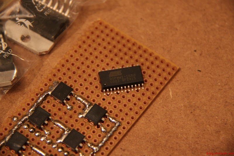
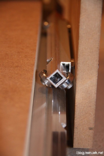
This picture was taken after the repair, which explains the flux residues ;-). The circuit you are seeing can be identified using an EPCOS resonator AppNote linked at the bottom of this article. The resonator (marked in picture) is a S+M R701, manufactured by Siemens Matsushita Components, a joint venture that later brought forth EPCOS. While there are other manufacturers like RFM, these models seem to be a pretty common brand for such keys as far as I have seen. Inside the metallic-ceramic casing is a parallel LC resonance circuit which has been precisely trimmed for a specific resonant frequency. The current types are mostly pin compatible to the old ones.

Just in case: Those resonators cost you a few cents at Farnell, but I would guess Digikey also has them. Use the datasheets to get the correct one for your frequency and pin layout. They are a real pain in the ass to solder by hand! But, to be fair, they were not really designed for it. Use hot air or reflow techniques if you can, or else heat the ground plane from the side, OR remove the resonator by applying a small amount of solder to the case top and heat it up completely. Take care not to rip the copper traces off the pcb, as the glue keeping them there becomes flexible when overheated. To solder on the new one, place it onto the cleaned pads and flow solder underneath the pins from the side, for each pin individually. Do not heat the resonator for too long. I did it like this twice, but as said – pain!

A good place to start is the EPCOS R920 resonator.

As I found out later, the resonator was perfectly working. I swapped it anyways – even swapped the old one back once I found the error – to make sure, but the real culprit was the HF output transistor which I have marked in the lower left.

How it works, in easy words: The signal generated by the microcontroller is a digital pulse signal containing the remote code. This signal is fed into the resonator through a resistor and a capacitor, and from the resonator back through said capacitor to the base of the output transistor. The resistor limits the output impedance of the controller pin to prevent it from clamping the transistor base to a fixed voltage and allow the resonator to overlay an AC component onto the DC voltage. Now, as the resonator…well…resonates at its designed frequency, excited by the impulse coming through the capacitor when the controller pin turns ON, the resonance waveform is coupled into the base of the transistor, which in turn amplifies it and pushes it out onto the antenna. Imagine repeatedly hitting a tuning fork with a small hammer and touching it to stop the vibration in a certain pattern while picking up the generated sound with a microphone to amplify it.

What you get is a high frequency signal during each high-level time of the remote code signal and no signal during each low-level time. This is called OOK, or on-off-keying. It can be seen as an extreme example of amplitude modulation (AM), and the principle is identical to the way TV remotes work – only that RF is used instead of IR light. There is a lot more theory behind this, you can look it up in dedicated books about high frequency circuits and transmitter circuits. As for this circuit, have a look at page 6 of the AppNote linked below. It features a standard circuit that very closely resembles my remote key, plus a detailed function explanation.

Back to the repair – checking the original transistor with a standard multimeter showed proper diode behaviour (meaning it was a bijunction npn or pnp transistor), but this is not always sufficient for a diagnosis of a working device in HF circuits. The output to the antenna (the copper strip along the left edge) appeared near-zero and the pulse signal after the coupling resistor was pretty deformed, too. With some remote keys you can test the RF output by holding a radio scanner set to 433,92 MHz or whatever frequency the key uses next to it and listening for pulsing tones/noise upon a key press. If you don’t get any response, you are either unable to hear the specific modulation (uncommon, as the modulation is pretty slow to ensure good reception) or the transmitter is (still) be broken. In the end, you probably have to find out by trial and error. Owning a GHz scope greatly simplifies the task, of course. I don’t, so I’d advise you to first swap the transistor and then the resonator. R/C/L are pretty uncommon to fail, whereas the transistor is sensitive to static electricity like most semiconductors. What you can measure, though, is the pulse signal from the controller.

Now, to get a suitable replacement, you can either buy a transistor that works for frequencies up to above the operating frequency of your device and has the same pinout – or you can simply go look for a cheap remote controllable wall socket, wireless weather station or the likes. Whatever you choose should use the same frequency, of course, and run on batteries. The probability of finding a suitable transistor inside such a transmitting device is very high. This will be the one nearest the feeding point of the antenna, like in the picture above. You’ll need to confirm the pinout by looking into the circuit or searching for a datasheet by the SMD marking on the case – if present.

I had to try two different transistors, the first one was probably already dead before transplantation (I already wondered why I never used that remote control). A second one worked like a charm! I have noted the designation of the found replacement in the picture above. The last thing to try is the range, but there is not much to gain with only about 3V of operating voltage – ideally, you’ll get whatever range the key had before. If the range is much less, the transistor is most likely not up to the job.

Remember that most car keys “forget” their assigned codes upon battery removal. You will need to reassign the key to your vehicle according to the proper method designated by the manufacturer.

Links:

Amp measurements (updated)

Here go the measurements. I use RMAA 5.5 free to do these.

All measurements were taken off an 5R6 load resistor. The maximum output power reached at 1 kHz sine into 5.6 ohms was 2.49 Weff resp. 4.97 Wpk, which is right on the money. Soft-clipping occurs right above that. I am not yet satisfied with the rise above 20 kHz, which I suspect to originate from a missing bypass cap in parallel to the feedback resistor. The cap short-circuits the feedback resistor at high frequencies to prevent oscillation (which currently occurs at 30-50 kHz when the volume isn’t turned all the way to the max).

The 50 Hz spike, on the contrary, is lower than I expected as I didn’t bother placing the output transformers away from the power transformer or putting them at an angle to prevent the magnetic fields from interfering. Another of those times when function follows form. Shielding in the wiring compartment could be improved a bit, though. Dunno if I should really photograph this mess.

UPDATE: And here comes a screen of the schematic. No need to do it in EAGLE as there is no PCB, the whole amp is air-wired. Enjoy.

The usual word of warning: This circuit operates at voltage levels of >= 275 Vdc at relatively low supply impedance, so please be aware that you build this circuit at your own risk, and proceed with caution! I am not responsible for any damage/injury that might occur related to this circuit.

As I already mentioned, there are lots of parallels to the linked amps from the last post. A few annotations concerning the schematic:

  • C5 is still missing in my case, estimate by trial and error.
  • Some parts dissipate a noteable amount of power, as marked – choose for at least 2W of dissipation to be on the safe side. You might want to oversize a bit here, to minimize aging of the parts due to thermal stress.
  • The coupling caps C3,C4 should be designed to handle voltages > 300 Vdc at least.
  • R9 is the loudspeaker, of course ;-)

Another piece of advice I learned during testing: If the connected audio source device is somewhat valuable, it is wise to install a suppressor diode directly across the input in such a way that is shorts high potential at the input to ground. In case any high voltage potential gets through the capacitor in form of a spike (like it did through a damaged socket in my case), this will at least save your soundcard a lot of undue stress.

EL84/EC86 Tube amp

This is a project I started some 5 years ago. It is the first tube-amp I built (and the only one so far), but I made an error in the calculations back then which led to absolutely nasty sound. No lows, oscillation and unproportional hi-end. Need me to say why it was sitting on the shelf ever since?

Yesterday I redid the calculations, now that I think I have a better understanding of how tubes want to be treated – and this time around I was successful. The frequency plot needs yet to be done, but from listening I like it very much so far. The tubes are also no longer the original ones, it was originally equipped with two EL83 from TESLA and two EF860. The EF860 did an okay job as a preamp but was very microphonic – that is, picking up vibrations from the casing – whereas the EL83 simply can’t handle much anode dissipation power, about half that of the EL84. Output power was limited to just above 2 Wpk.

Some basic facts:

  • JJ EL 84 power pentode as output tube, single ended configuration
  • ORION EC 86 single-triode as preamp tube
  • 275V anode operating voltage
  • HSGM (german company) output transformers for EL84 SE
  • Total amplification preamp ~ 10-fold (optimized for consumer audio devices)
  • Global feedback including output transformers
  • Peak output power ~ 4 W
  • Beech wood & brushed aluminum casing
  • And the blue tape on the transformers is there to creep off anyone (me) thinking of accidentally sucking power off the transformer rails with his finger or other body parts while ogling it in the dark. This is not to become a permanent aesthetic feature, but there are no transformer caps available for this type. I will build something out of epoxide PCB, I guess.

I will put my schematic, the bode plot and exact part types up here in an extra post as soon as I get my scanner to work. Until then, I advise you to visit the following sources which helped me a lot and are always an inspiration for me. Dig through the news section, there are some GREAT projects.

  • Pentode SE amp using 5B/110M tubes (german reader’s project on Jogis Roehrenbude, my schematic has become very similar. Great explanation of the necessary calculations)

Seems like my biggest mistake in the past was not to account for the voltage drop over the output transformer, induced by the bias current. *facepalm* I totally forgot that.

See also: Second post, containing schematics & measurements…

Das Blog und der Server [DE]

Die Probleme zwischen diesem WordPress 3.1.3 hier und dem Telekomserver sind endlich gelöst!

Sieht so aus als war ich die ganze Zeit zu blind um zu bemerken, dass die Umstellung von PHP4 auf PHP5, die über eine .config-Datei möglich ist, für jeden Ordner getrennt passieren muss. Dasselbe gilt für jede Einstellung über eine php.ini – das gehört alles in den Hauptordner vom Blog, nicht das Wurzelverzeichnis vom Webspace. Und ich hab’ die ganze Zeit nicht bemerkt, dass im Hintergrund noch PHP4 werkelt.

Als Hinweis – bei mir traten folgende Symptome auf:

  • Uploads von Bildern laufen durch, danach steht aber beim Einbinden in einen Post oder eine Galerie nur die Größe “Full size (0 x 0)” zur Verfügung.
  • Schwierigkeiten bei verschiedenen Skripten und Plugins die PHP5 erwartet haben – logisch irgendwie. Speziell der Plugin-Updater schmiert ständig ab.
  • Sehr gehäufte Fehler wie

    PHP Fatal error: Allowed memory size of 33554432 bytes exhausted (tried to allocate 5275922 bytes) in /home/www/wp-includes/media.php on line 254

    in der entsprechenden Logdatei. Außerdem Hinweise auf versuchte Speichervergrößerungen durch WordPress, die verhindert wurden.

  • GZIP wehrt sich vehement gegen alle Versuche, das Blog etwas zu schrumpfen. Abhilfe schafft da ein kleiner Trick (siehe unten), aber da PHP4 aussterben sollte ist der eigentlich irrelevant. Mit PHP5 funktioniert jedenfalls jedes beliebige WP-Plugin dafür.

Mann, komme ich mir grade doof vor ;-) An bestimmten Tagen sieht man den Wald vor Bäumen nicht, und am Tag danach versteht man auffallend gut woher das Sprichwort kommt. Immerhin kann ich jetzt endlich die restlichen Designänderungen umsetzen, ohne dass mir seltsame Fehler gleich wieder einen Strich durch die Rechnung machen.

Dank geht hierbei speziell an faulthiel, der in seinem Blog eine ansehnliche Sammlung von Tipps und Tricks rund um WordPress bei der Telekom zusammengestellt hat.

Die Konfiguration vom Webspace verlangt am Ende zwar etwas mehr Aufmerksamkeit als anderswo, aber ansonsten läuft das Blog wie geschmiert.

Weitere Links zu passenden Themen:

“Erhöhung php memory limit?” im Telekomforum

“PHP.ini & memory_limit” im Telekomforum

“Gzip without gzip” auf dieser Seite

Workbench #1

LED driver again

The first version of the LED switching driver just exhaled a portion of magic smoke. The IC is neither the culprit nor the victim, there must have been a short somewhere else. The sense resistor was fried and acted as a fuse, but it wasn’t fast enough to prevent the current blowing another transistor on the motherboard that switches power to the backlight. Funny, didn’t even know there was such a thing. Maybe that explains the weird current shortages at the LED driver input that caused some of the flickering. The LT chip seems to have survived just fine, again.

Whoops, forgot to mention: Yes, it has been running ever since the last post about the topic ;-) so far, so good.

Anyways, gotta do this one again. To counter the problems with flickering, the new driver will run from 5V of the HDD/USB supply, operating in pure boost mode. Stepping from 5V to 9.6V will never cause it to even get near the crossover point where it would need to switch from boost to buck mode, and there will never be a lack of control range.

To explain that part, remember that the LT3518 runs in fixed frequency mode and varies only the pulse/pause ratio of the switch that draws power through the inductor. Let’s also assume we are in buck (stepdown) mode and the output current (LED current) is the variable the IC is trying to regulate. As the output voltage of a step-down converter is proportional to the on-time of the switch, the switch needs to be open all the time when the input voltage drops to or below the needed output voltage (that is, the voltage required to drive the desired LED current). Now, the LT3518 has a limitation in its pulse-duration caused by the design of its internal circuits, which in this case results in a maximum on-time of about 92%. If the required on-time rises above that, the IC can no longer guarantee proper function and instead of opening the switch permanently the regulating circuit begins to glitch, which results in flickering, low LED current and whatever else. It is not a danger for the LEDs though, because whatever happens, a step-up converter can never reach a voltage higher than its input.

I admit that I was kind of slacking off to assume it would work alright somehow – well, it didn’t ;-) Lesson learned, that’s why I don’t mind this happening. Sometimes doing it wrong is the only guarantee you’ll do it right the next time. The next version of the driver circuit will come with full eagle layouts and stuff; so please don’t get too hooked to the old design. It is only usable if you can guarantee a, let’s say, 2V surplus over the typical output voltage at the input all the time.

The new design will probably be done and up here ’til Sunday this week, and there will be some extra stuff with the CNC (stepper driver ICs arrived, some work on the axis’)

CNC – Step 2

I remade the linear bearing sleds today, the previous ones were not precise enough – they were only the proof of concept anyway. The new ones glide on the rails as if they were not touching at all, VERY nice feeling if you lean on the bridge support with approx. 10 kg and slide it back and forth. No bumps, just smooooooooth metal! No clue how precise they are in terms of height differences and imprefections though, but there is a little potential to adjust if something should be too far off.

The portal looks very good so far! BUT….the cross-bar is skewed -.- Not by much, only one or two degrees around the length-axis, but it is enough for the right bearing sled to not sit on the rail properly. I can force it on, of course, but that is not the great idea here as the sleds should fit snugly on the rails without any force besides its own weight applied. In the beginning MDF was planned for this part, but I settled for beech wood instead. Best option here is to dump the current one, buy a precise MDF cut tomorrow and stuff the beech back into the scraps box for some future case build. After that, if the dimensions and angles of the portal as a whole are within tolerances, two more bearing sleds are needed to keep the portal on the rails while moving and when milling action occurs. Two more of the exact same type should suffice, but maybe some kind of spring-loaded mount would be better for long-term stability.

The side supports of the portal will be redone after the mill is completed. As will some other parts, probably. I will have access to a cnc mill then, so why not do the holes and cut-outs a little more precise ;-)